Power Line Carrier Communication (PLCC) is used for the purpose of protection of line and communication between the two stations. Two different PLCC channels are used for the protection of a single line. This is the reason, you will notice that wave traps are normally installed in R and B phase of transmission line. The two wave traps corresponds to two different channels of PLCC. There are two PLCC Panels corresponding to two channels i.e. Channel-1 (CH-1) and Channel-2 (CH-2) for sending / receiving signals for each line. Thus for any single line there shall be three PLCC Panels, Channel-1, Channel-2 and Speech channel.
Carrier Signal is sent through these two channels to the remote end in case of actuation of Zone-1 protection and Direct Trip (DT) signal is sent in the event of three phase trip. Similarly, Carrier Signal or DT signal is received from the remote end via dedicated PLCC Panels.
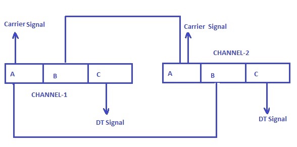
In each Channel, three codes are used i.e. code A, B and C. Code A and B are meant for Carrier Signals while code C is dedicated for Direct Trip Signal.
Code A of Channel-1 is generally looped with Code B of CH-2. Similarly Code A of CH-2 is looped with Code A of CH-1. Therefore when carrier signal is received from protection relay of one end in any one of the Channel, then the signal to remote end will be sent through both the channels i.e. CH-1 and CH-2. Looping of code C is normally not done for Direct Trip.
Features of PLCC Panels:
A PLCC Panel has two display units as shown in figure below.
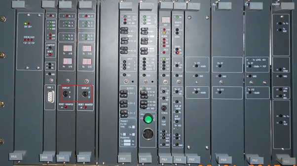
- The position of knob corresponds to the code. If the knob is selected at A at PLCC Channel-1 and carrier is sent through Channel-1 then the count in code A of Channel-1 shall increase by 1. As code A of Channel-1 and code B of channel-2 are looped, therefore in Channel-2, the count reading for code B shall also be increased by 1.
- Similarly, if the knob is selected at B at PLCC Channel-2, and carrier is sent through Channel-2 then the count in code A of Channel-2 and Code B of Channel-1 shall increase by 1.
- Normally the knob in Channel-1 shall be kept at A while for Channel-2, it shall be at B.
- As DT code is not looped for Channel-1 and Channel-2, therefore the position of knob for DT display unit shall remain at position C.
Nice explanation for almost all articles! Keep up the good work!!👍
Thanks so much.