As the name of the test specifies, in Blocked Rotor Test, rotor of Induction Motor is blocked by external means so that it cannot rotate. The Blocked Rotor Test of Induction Motor is similar to the short circuit test of a transformer.
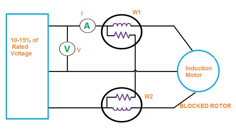
As in Transformer short circuit test, we apply a voltage which can circulate rated current in the winding, likewise in Blocked Rotor Test we apply a Voltage to the Stator winding of an Induction Motor by using VARIAC so that rated current flows through the stator winding. The voltage required to circulate the rated current through the Stator winding is around 10-15% of the rated voltage.
Since this voltage required to pass rated current through the stator winding under blocked rotor condition is only about 10 to 15 % of the rated stator voltage, the core losses during the Block Rotor test is negligible, mind that core loss is roughly directly proportional to the square of Voltage. Thus the wattmeter reading would effectively give the sum of stator and rotor copper loss. This wattmeter reading is then used determine the leakage impedance of Induction Motor as shown in figure below.
Thus Blocked Rotor Test is performed on an Induction motor to calculate the leakage impedance of Induction Motor.
Form the figure above, as the rotor is blocked to rotate, mechanical loss will be negligible and therefore,
Total Power input Pin= Stator Ohmic Loss + Rotor Ohmic Loss
= W1 + W2
The input voltage V and Input phase current I are recorded. Here V = Line Voltage
But Pin = I2Reqs
where Reqs = Equivalent Resistance of Induction Motor referred to Stator side.
Therefore,
Reqs = Pin/I2
Now, Blocked Rotor Impedance Zeq = Input Voltage / Input Current
= Vph/I
So,
Equivalent Blocked Rotor Reactance X =
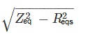
As, stator reactance X1and rotor reactance per phase referred to stator X2 are normally assumed equal, hence
X1 = X2=X/2
DC resistance of Stator winding is measured just after the Blocked Rotor test and the value obtained is multiplied by 1.1 to 1.3 to get the effective resistance of stator winding. Thus if R1 be the stator winding resistance and R2 the rotor winding resistance, then
R2 ≈ Reqs– R1 approximately.
In this way, the leakage impedance of Induction Motor is calculated using Blocked Rotor Test.
What is important for Blocked Rotor Test?
It should always be understand that, for large Motor of rating more than 20 kW if the Induction Motor characteristics is required near s=1 i.e. for getting an idea of starting torque, then Blocked Rotor Test shall be performed at line frequency as the rotor frequency sf = f =line frequency.
But if we need Induction Motor characteristics near synchronous speed the as the rotor frequency becomes sf therefore Blocked Rotor Test shall be performed at sf frequency not at line frequency.
Check this out for Electrical Machine. I will sugest to read this Book many times instead of reading many books one time. It is concept wise a great book and objectives & subjective questions at the end of the Book is very important and helpful for different kind of Exams.
Thank you!