Capability Curve of Generator defines the boundaries within which it can deliver reactive power continuously without overheating. Generator rating is specified in terms of MVA and power factor at a particular terminal voltage. Active power delivered by generator is only limited by the power delivering capability of turbine. But the reactive power which a generator can deliver continuously without over heating is governed by three limits: Armature Current Limit, Field Current Limit and End Part Heating Limit.
Armature Current Limit
Armature current is the load current in the stator winding. Let the armature current is I. This current will lead to heating of stator winding due to ohmic loss I2R in the resistance of stator winding. This means that, a constraint is put by the limit of cooling of generator stator winding. Ideally there is a balance between the heat produced by I2R loss and cooling of stator winding. But if the heating of stator winding is more than its cooling then it will lead to excessive heating and consequent damage to armature of generator.
Therefore the armature current of Generator shall not exceed the design maximum value. Let’s us now try to plot this armature current limit on P-Q plane. As we know that complex power is given as
P+jQ = VI* where I* is conjugate of I.
= VI(CosØ + jSinØ)
Taking modulus to both sides, we get
P2 + Q2 = (VI)2 which is an equation of circle with center at origin and of radius VI as shown below.

The above circle represent the armature current heating limit on generator operation. Generator shall always be operated under the circle to avoid heating.
Field Current Limit
A maximum limit on the value of field current is imposed by the heating in the field winding due to If2R loss where R is the resistance of field winding. This means that generator can only supply / absorb a fixed maximum value of reactive power. We know that, E = Vt + jIXs
where E is no load excitation voltage, Vt is terminal voltage, I is load current and Xs is synchronous impedance of Generator. The above equation can be represented by the phasor as shown below.
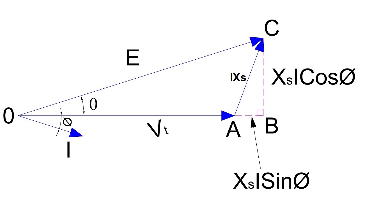
From the above phasor,
XsICosØ = ESinθ
⇒ ICosØ = (ESinθ) / Xs…………………………. (1)
XsISinØ = ECosθ – Vt
⇒ ISinØ = [(ECosθ) / Xs] – Vt……………………………(2)
Now, active and reactive power delivered by Generator can be calculated as
P = VtICosØ
= (EVtSinθ) / Xs …….[from equation (1)]
⇒ P = (EVtSinθ) / Xs …………….(3)
Note that the above equation of active power is not new one rather it is very famous equation where θ is load angle.
Q = VtISinØ
= (EVtCosθ) / Xs –Vt2/Xs…….[from equation (2)]
⇒ (Q + Vt2/Xs) = (EVtCosθ) / Xs ……..(4)
Squaring (3) and (4) and then adding we get,
P2 + (Q + Vt2/Xs)2 = (EVt / Xs)2
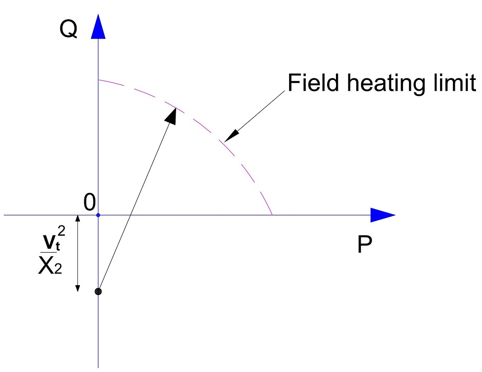
The above circle represents the field heating limit. Generator must be operated within this circle to avoid field heating.
End part heating puts a limit on generator reactive power when machine is operating under leading power factor condition. Leading power factor means, the machine is under excited, therefore field current will increase to meet the required working flux. This will cause more end flux in the machine which will link with the stator lamination to cause eddy current heating. Please read End Part Heating for detail.
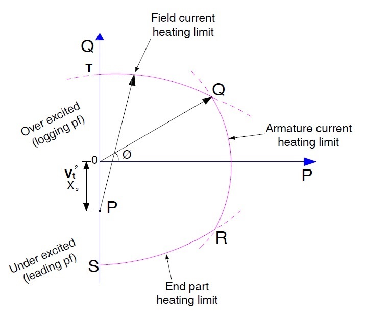
1) Armature heating and field heating limits are shown by curve QR and QT respectively. Both these curve cut at point Q which means the generator shall be operated at this point under lagging load condition.
2) End part heating is shown by curve RS for leading load condition. It shall be noted that armature heating limit and end part heating limit curves cut each other at point R. This point is the point of operation of generator under leading load condition.
3) Generator operation shall always be confined within the capability curve at all the time else it may damage due to overheating.
4) Capability Curve is supplied by the manufacturer and works as a guideline for operator of generator.
5) Capability Curve is all about heating of different parts. This means that if the cooling of machine is increased then the limits of generator operation will also increase. This means the individual limits will increase and the operation boundary will broaden.
Please explain different modes of generator in practical scenario.
There is a typo in the full capability curve, it should say “lagging” it says “logging”
you are genius Pablo D lopez
thats good…as far as i know this used with synchronus generators having cylndrical
rotor,….isit valid for wound rotor also?