The modern loads are designed to operate at satisfactorily at one voltage level. It is therefore of great importance to keep the consumers terminal voltage within a prescribed limits. The Transformers output voltage and hence the terminal voltage of the consumer can be controlled by using tap either on primary or secondary side of Transformer.
- If we increase the Primary Number of Turns N1, output voltage of Transformer V2decreases.
- If we decrease the Primary Number of Turns N1, output voltage of Transformer V2increases.
- If we increase the Secondary Number of Turns N2, output voltage of Transformer V2increases.
- If we decrease the Secondary Number of Turns N2, output voltage of Transformer V2decreases.
- Transformer Taps are provided on HV side as in this case Tag changing Gera will handle low current and chance of sparking will be less.
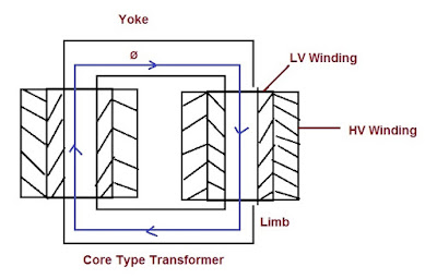
- If we see the construction of Transformer, we will observe that LV winding are placed just after the core to limit the insulation requirement to be provided and HV winding are placed on the LV winding. Thus it is quite difficult to provide the Taps on the LV winding of the Transformer.
Now after deciding the side where Tap is to be provided in Transformer, next question is that whether Tap shall be provided in the center of the winding or at the end of the winding?
A general sense says that Tap shall be provided in the middle of the winding because in this case the forces on the winding will be less.
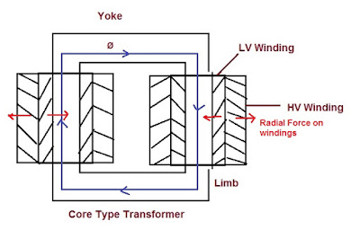
Since the current flowing in the Primary and Secondary coils are in opposite direction, these currents interact with the leakage flux in between the two windings and produce a radial force repelling each other as shown in the figure below.
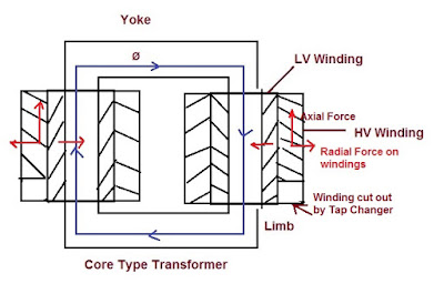
Now, suppose the winding is tapped at one end. When some of the winding is cut out by tap changer, axial force in addition to radial force is also developed as shown in figure below.
Under short circuit condition, the axial force tending to compress the winding against the core is very large which may damage the winding insulation. In order to eliminate this, physical position of the Tapped winding should be in the middle of the Transformer winding so that no axial force arises after some of the turns are cut out.
Thank you!


