As we know, both Snubber Circuit and Crowbar Circuit is used for protection against Overvoltage using Thyristor but they way they protect the Thyristor has some difference.
Crowbar Circuit:
Power supplies are normally reliable, but if they fail then they can cause significant damage to the circuitry they supply. To protect against this it is possible to add a simple SCR overvoltage crowbar protection circuit. Crowbar protection is a fail-safe protection mechanism which short circuits the output of a power supply under failure conditions such as over voltage. Here Fail-Safe means, in case of failure the system will go to safe condition. Crowbar protection can also refer to a circuit which has its sole purpose to cause a fuse to blow by subjecting it to high current. Figure below shows a typical Crowbar Circuit.
Above Crowbar Circuit uses an 8V supply and has its overvoltage protection set at 9.1V but this overvoltage setting can be adjusted by changing to the zener diode with the preferred voltage. At 9.1V, the zener diode ZD1 starts to conducts and cause a trigger signal to switch on the thyristor Q1.
The fuse F1 blows up once the current exceeds its rated 250mA. Capacitor C1 is used to take care of the small voltage spikes, noise and other harmless fluctuations which may erroneously trigger the circuit.
In an active Crowbar the fuse is not designed to blow and the protection removes the short once transient is over, allowing the system to resume its normal operation. An active protection circuit does not use the thyristor for the short circuiting but they utilize a Gate Turn Off Thyristor (GTO), a transistor or a forced commutated thyristor, all of which can be switched off using an appropriate signal.
Snubber Circuit:
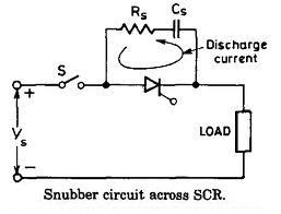
Snubber Circuit is used for protection of Thyristors against spurious dv/dt, which can cause false triggering.
As shown in figure above, when S is closed a high voltage appears across the circuit arrangement and at t=0+ capacitor will act as short circuit which will make voltage across the SCR equals to zero, and after some time when voltage across C starts to build up it builds up in a manner that this dv/dt across SCR is less than the specified value, so the possibility of false triggering is eliminated, and Rs here acts as a current limiter.

