V-curve and power factor control of generator are closely related to each other. V-curve of Generator is basically a plot of variation of armature current with the change in field current. For a constant power, V-curve can only be obtained for generator connected to infinite bus / grid. There does not exists any such curve for an isolated generator.
For synchronous generator with zero armature winding resistance the equation of voltage is given as
Ef = Vt + jIaXs
From the above equation, we can draw phasor relation between the excitation voltage Ef and terminal voltage Vt as shown in figure below.
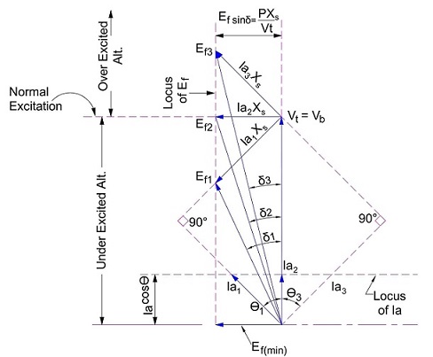
From the above phasor, we can have three cases.
Case1: When Excitation voltage is Ef1.
As clear from the phasor, when excitation voltage is Ef1, the Generator is underexcited and load current Ia1 is leading the Vt = Vb = Infinite bus voltage. Therefore we can say that, an underexcited Generator connected to infinite bus operates at leading power factor and absorbs the reactive power from the Grid.
Case2: When Excitation voltage is Ef2.
With increase in field current, excitation emf rises. For excitation emf Ef2, load current Ia2 is in phase with the terminal voltage Vt = Vb = Infinite Bus Voltage. Thus generator is operating at unity power factor and as clear from the phasor, Generator is normally excited. This means that, Generator will neither absorb nor deliver reactive power from / to Grid.
Case3: When Excitation voltage is Ef3.
For Ef3 more than Ef2, load current Ia3 lags behind the terminal voltage Vt. In this case, the generator is overexcited and therefore delivers the reactive power to the Grid / Infinite Bus.
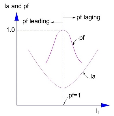
V-Curve of Generator
After having the concept behind the three cases discussed, it is better to plot a curve between field current and armature current. This curve is popularly known as V-curve of Generator connected to infinite bus.
“V-curve of Generator is a plot of variation of armature current with the change in field current. “ This curve for generator connected to infinite bus is show below.
Difference in behaviors of Isolated Generator from that Connected to Grid
The difference between the behaviors of isolated generator to that that of generator connected to an infinite bus can be summarized as below.
Speed
When speed of an isolated generator is increased, its excitation voltage and terminal voltage both increases as Ef = 1.414πfNphØ. Its output frequency f = PN/120 also increases and therefore its synchronous reactance increases.
But the speed of generator connected to the infinite bus or grid cannot be altered as its operating frequency and therefore speed is governed by the frequency of Grid or infinite bus. Further the terminal voltage is fixed by the grid voltage.
Field Excitation
Increasing field current for isolated generator, increases the excitation voltage and therefore the terminal voltage. Thus the operating power factor is not dependent on the excitation rather it only depend on the nature of load conned to the generator.
But for generator synchronized with grid, increasing excitation will change the operating power factor of generator from leading to lagging as clear from the V-curve.
Prime Mover Input
Increasing the Prime Mover input increases the speed of an isolated generator. Due to increased speed, the excitation emf and hence terminal voltage rises. Therefore power output P = EfVtSinδ / Xs increases.
But for Generator connected to grid, increase in prime move input do not alter the speed of generator and hence excitation emf & terminal voltage. Rather active power delivered to the grid rises as the load angle increases due to shift away Ef from the grid voltage Vt = Vb.