We will discuss how to measure Capacitance and Dissipation Factor. Capacitance is measured by using Schering Bridge. What is this Schering Bridge? First we will discuss how to balance a bridge.

As we know for balanced bridge,
there should not be any current through the detector which means the potential difference across the detector is zero.
I1Z1= I2Z2………………………………………………(1)
But I1 = I3 = E / (Z1+Z3), E is the supply voltage.
I2= I4 = E / (Z2+Z4)
Therefore, from (1),
Z1Z4 = Z2Z3 for bridge to be balanced.
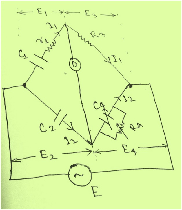
The connection and phasor diagram of Schering Bridge under balanced condition is shown in figure below.
Phasor Diagram:

Let, C1 = Test Capacitor (Capacitor whose capacitance is to be measured)
r1 = A series resistance representing loss in capacitor C1
C2 = A standard capacitor. This capacitor may be air or gas capacitor and therefore loss free. That is why no series resistor in C2.
R3 = A resistance
C4 = A variable capacitor
R4 = A variable resistance in parallel with C4
So, in our case for Schering Bridge to be balance,
Z1Z4 = Z2Z3
(r1+1/jwC1){R4/(1+jwC4R4)} = R3/(jwC2)
Or, (r1+1/jwC1) R4 = R3(1+jwC4R4)/jwC2
r1R4 – jR4/wC1= -jR3/wC2 + R3R4C4/C2
Equating the real and imaginary part, we get
r1 = R3C4/C2
and C1 = C2R4/ R3
and tanδ = wC1r1= w(C2R4/R3)(R3C4/C2) = wC4R4.
Therefore, we can find the value of Test capacitor by balancing the Schering Bridge. Schering Bridge is widely used for Capacitance and Dissipation Factor measurement. It is used for the measurement of properties of Insulators, capacitor bushing, insulation oils and other insulating materials.
There are three modes of testing, Ungrounded Specimen Test(UST), Grounded Specimen Test(GST) and Grounded Specimen Test-Guard(GST-G).
UST mode of test is used where the test object is not grounded anywhere. In this case High Voltage(HV) lead is connected to one point of the test object and Low Voltage lead to the another point. For example, HV lead is connected to HV winding of transformer and LV leas to the LV winding. In UST Mode, there is only one way for leakage current to return to the Test Kit that is only through the LV lead the Test Kit analyses this return current and displays the value of Capacitance and tanδ. Mind that Schering Bridge is balanced in the Kit internals only.
GST mode of test is used for the test object which is grounded at any point. Practically, if equipment is installed then 99% chance is that the equipment will be grounded and therefore for the purpose of measurement of Capacitance and tanδ, GST mode is used. In this mode the HV lead is connected to one terminal of the test object and LV lead to the ground. Therefore, the Test it analyses the return leakage current from the ground and displays the Capacitance and tanδ.
GST-Guard mode of Test is used where we want to eliminate the effect of capacitance because of the presence of other circuit. It should be bear in mind that the value tanδ in GST mode is equal to the sum of value in UST and GST-guard mode.
The test object whose tanδ is to be measured is isolated first from the system. Then it is connected to the Test kit. After that a very low frequency normal voltage is applied across the test object. If the value of tanδ agrees with the Factory Test Report of the test object then voltage is increased to 1.5 to 2 times the rated voltage and value of tanδ is noted. In the same manner the Voltage is increased in steps and value of tanδ is recorded. The values obtained are either matched with the Factory Test Report or Historical Data of the test object. If the values matched with slight deviation then we conclude that the test object is healthy else damaged.
In case we don’t have any Historical Data or Factory Test Report, then we plot the value of tanδ with respect to applied voltage. If there is no or slight variation in the value of tanδ then we can say that test object is healthy. As tanδ doesn’t depend on applied voltage or frequency.
A typical curve for Healthy test object and Unhealthy test object will look like,

From the curve, it is clear that for good test object there is slight change in the value of tanδ w.r.t voltage while the same is not true for unhealthy test object. Tanδ increases with voltage for bad test object which in turn mean, ingress of moisture, dirt or impurity in the dielectric of Capacitor. It should also be noted that if it is seen that tanδ is increasing with voltage then we should stop test as applying more higher voltage may lead to Dielectric Breakdown.
Why Low Frequency Voltage?
It is important to note that Low Frequency Voltage is applied in tanδ test by Test Kit. There are two benefits of this:
a) Low frequency means more 1/wC, as w = 2πf, which means that the Reactance offered by the Capacitor will be High. Due to High Impedance the Capacitor will draw less current from the Test Kit at a particular given voltage. Therefore the KVA requirement of the Test Kit will be reduced.
b) Due to low frequency the value of tanδ= 1/2πfCr, will be high and hence easier to measure.
That’s all I wanted to share. Please comment if you have any suggestion / queries.
For Video Tutorial on this topic click here.
It is really great write up. I fully understood measurement of Tan Delta using Schering Bridge. Video tutorial helped me a lot. Can you please help me to understand Kelvin Double Bridge for measuring small resistance? Thank you in advance!
Thanks Danna! I will publish post on Kelvin Double bridge. Just subscribe and you will get regular updates on new topics.
thank u
Can a Current transformer be used to reduce the current magnitude to be fed to Scheringe bridge.
If yes, how the tan delta value be calculated?