What is Point on Wave Controller / Switch?
Point on Wave Switch (PoW) , often called Point on Wave Controller is a high speed microprocessor based relay used for the controlled switching of circuit breaker of HVAC system. Controlled switching refers to open or close a breaker at a pre-determined point on the voltage waveform. This controller is used for switching of Shunt Reactors, Transmission Lines, Power Transformers and Capacitor Bank.
Why Controlled Switching is required?
Random switching of equipment may lead to high frequency over-voltage transient and inrush current. This in turn may stress the equipment and leads to rapid aging. It is suggested to read Transformer Inrush Current for better understanding of inrush phenomenon.
How Controlled Switching by Point on Wave Switch / PoW Controller achieved?
Point on Wave Switch basically synchronizes the random closing / opening input order so that individual poles of the breaker get close / open at pre-determined point on reference voltage waveform. Figure below shows the simplified diagram of PoW controller operation.

The above figure shows the use of PoW controller for switching Shunt Reactor. It can be easily seen that, a Point on Wave controller takes the following inputs:
Source side PT supply – Only one phase i.e. R-N of source side PT supply is taken for reference. This PT supply acts as a reference for system voltage and PoW controller decides the target point on this system voltage. In case of Shunt Reactor switching to minimize the inrush current, it is desirable to close the breaker at voltage peak. Since the load is reactive in nature, therefore closing the breaker at voltage peak will cause the shunt reactor to take zero current (current through an inductor lags by 90°) and therefore the transients in current will be minimized.
CB Parameter – For PoW controller to decide the point of switching on the system voltage waveform, it is necessary for it to know the breaker opening and closing time. Therefore, breaker closing and tripping parameter is fed. Breaker timing is obtained through the timing test which is carried out along with DCRM test.
CT Input – CT input to PoW controller serves the purpose for analysis of load current upon closing / opening of breaker. It is also used for the estimation of breaker opening / closing time. It shall be noted at this point that breaker closing is the instant at which pre-arcing at take place. Pre-arcing take place before the actual closing of mechanical contacts. Normally pre-arcing time is 2ms. Similarly for opening operating, breaker opening time is the instant between mechanical contacts open and arc extinguishes. Therefore arcing time must be considered for determination of target point. Normally, arcing time is 6 ms.
Working Principle of Point on Wave Switch
When a random closing / opening command is given to the breaker through control switch, PoW receives the command and process it before issuing the closing / opening command to the breaker. It introduces a time delay between the issue of random command from control switch to the issue of command by PoW Switch as shown in figure below. In this time period, the controller does the necessary calculation such that breaker may close at defined point on reference voltage waveform. For this calculation, breaker operating time is considered and then PoW issues command in such a time that breaker may close at the target point. In the figure below, target point is at voltage zero.

Let us consider an example for better understanding. Let us suppose that breaker closing time is 104.78 ms and it is used for switching shunt reactor. Therefore our target point shall be voltage peak. Point on Wave Switch has its own time delay and it adjusts its delay in such a way that the sum of PoW delay and Breaker closing time corresponds to voltage peak. Suppose the controller delay be 37.80 ms, therefore expected target point shall be (Breaker closure time + Controller Delay = 104.78+37.80) 142.58 ms. But actual closure of breaker means the instant of time where current start flowing through the circuit. Thus pre-arcing time shall be taken into consideration. Assuming pre-arcing time to be 2 ms, the target point shall be 140.58 ms. Figure below shows the graph of switching instant for Shunt Reactor.
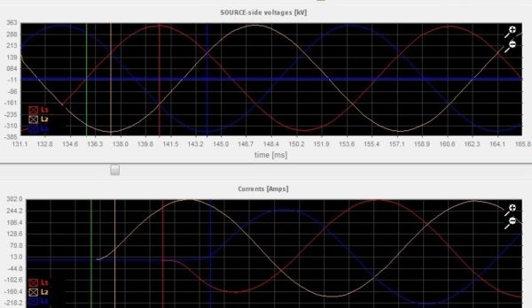
Following points shall be noted from the above graph:
- The target point for shunt reactor is at voltage peak to limit inrush current.
- PoW Switch determines the target point for Y and B phase assuming balanced three phase voltage as only one phase voltage input is given to it. Thus if R phase voltage is assumed reference then
VY = VmSin(ωt-120°)
VB = VmSin(ωt+120°)
- As voltage peak either positive or negative for Y phase is occurring first, therefore closing command to Y pole of breaker will be issued first. Thereafter R and at last B pole will close. Thus the difference in target point for two consecutive phases will be (30° = 10 ms / 6) 1.67 ms as evident from the graph above.
- Carefully observe the current curve and see how smooth current transition is taking place. It can be realized from the above graph that how inrush current is limited.
Adaptive Nature of Point on Wave Switch
As we know that, Breaker opening and closing time changes with time and aging. Further it is also affected by the environmental condition. Therefore it is necessary to compensate for these. Compensation for environmental condition is accounted by giving ambient temperature input to Point on Wave Switch.
For accounting change in breaker operating time due aging, PoW is made adaptive. Adaptive means, it can adapt its timing as per the previous switching data so that required target point can be achieved.
Point on Wave Switch Bypass Feature
A provision for bypassing PoW switch is generally provided by the manufacturer. The controller gets automatically bypassed in case of internal fault in it. For manual bypass, two hand switches CLOSE and TRIP with IN & OUT positions are provided to bypass closing and tripping operation of breaker manually when required.
It shall be noted that, in case of protection breaker always trips on PoW bypass mode. This is done to avoid for any intentional introduction of time delay for clearing fault.
This post just gives the basic idea of Point on Wave Switch / Controller. I tried my best to describe the basic idea behind it. Your value addition and suggestion is welcome. Thank you!
I was searching for this good job, short and precise. What will be switching instant for line & GT? I think current zero sensing.
Excellent post, you explained it smoothly.
Thank you! Please share the post.
I want to know the detailed procedure how i test POW function if I don’t have kit to test.
also I am performing tests on Typhoon HIL .would you please explain how i can perform this test on Numerical relay testing on Typhoon
Hello, First of all thank you very much for your precise teaching. I am forever grateful. I have one point to say: The diagram and pictures which u put up in the blog is not visible. Requesting you to kindly take a look at this problem. I am currently using the latest version of Edge & Google.
How does PoW works when you have a fault in the system and relay trips the breaker or in other words PoW controller is bypassed when relay trips the breaker? During the next closing cycle after a relay operation, does the PoW controller kicks in and finds the zero crossing Voltage reference?