In last post Load Encroachment on Distance Protection, we observed that low value of Impedance Z arise due to voltage instability or transients associated with electromechanical oscillations of rotors of synchronous machines after a major disturbance like the faults. This can introduce nuisance tripping. Such tripping is known as tripping on Power Swings. In this post we will discuss on Power Swing in detail.
Power swings is defined as oscillation in active and reactive power flows on a transmission line consequent to a large disturbance like a fault. The oscillation in the apparent power and bus voltages are seen by the Relay as an impedance swing on the R-X plane. If the impedance trajectory enters the Relay zone and if stays there for sufficiently long time, then the relay will issue a trip decision on Power Swing. Tripping on Power Swings is not desirable.
For understanding the phenomenon of Power Swing, consider two machine system connected by Transmission Line having Impedance ZL as shown in figure below.
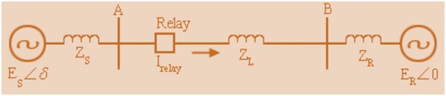
Here ES and ERare the generator voltages at two ends and we assume that the system is purely reactive. Also assume that power is flowing from A to B therefore voltage ES leads ER by an angle δ. The relay on which Power Swing impact is to be studied is located at A. We first draw the Power Angle Curve for the above system.
Power Angle Curve for the above two Machine System:

The system is operating at initial steady operating point A with Pmo as output power and δ0as initial rotor angle.
Now, suppose that a self clearing transient three phase short circuit fault occurs on the line. During the fault, the electrical output power drops to zero (because Voltage is reducing to zero). Suppose after time t fault is cleared. So after this the operation of machine jumps back to the sinusoidal curve.
As input supply to the rotor of Generator remains constant but output electrical power reduces to zero hence rotor will accelerate. This rotor acceleration advances rotor angle to δ1where the output power becomes equal to the rated power so no acceleration at this point but because of inertia the rotor will move further to an angle δmaxwith deceleration. At δmax the speed of rotor becomes equal to the speed of infinite bus but at this point the output power is more than the turbine output hence rotor will decelerate and the rotor speed goes down relative to infinite bus till it reaches δ1 but because of inertia the torque angle continues to decrease till δ0. This cycle repeats itself if damping is not present. This is called Power Swing. In practice because of presence of damping the machine operates at δ1.
As per equal area criteria, the rotor will swing up to maximum rotor angle δmax, such that,
Accelerating Area (A1) = Decelerating Area (A2)
By solving the above equal area criteria, we will get
δmax = f (Pmo, t)
Thus the maximum torque angle is a function of output power and fault clearing time.
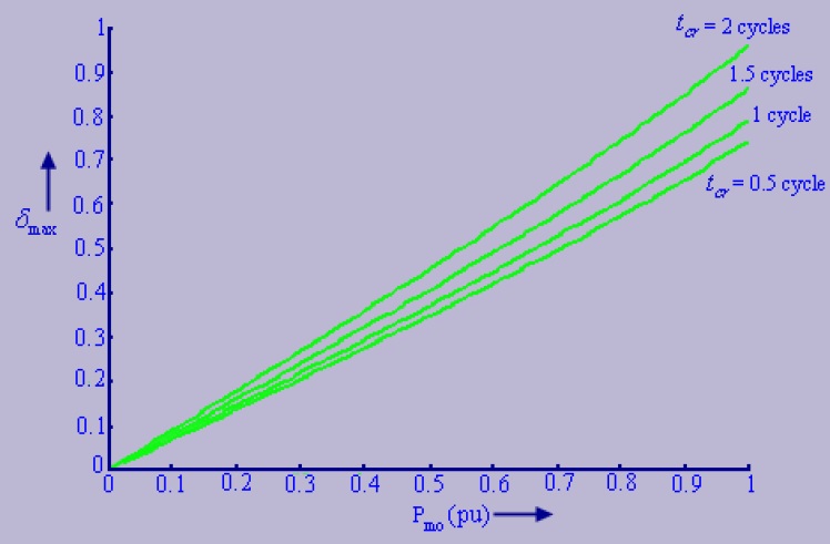
It is clear from the above figure that maximum torque angle increases as the Pmoand fault clearing time t increases.
So far we discussed about Power Swing and behavior of machine on Power Swing. Now we will discuss the impact of Power Swing on Distance Relaying in next post. So be there and follow…….
Thank you!
Thank you very much for simplifying a complicated topic.
What will be the impact on large generating station, say two generating stations of 1100 MW each connected to 500 kv network via 4 transmissions lines and two buses using 1.5 breaker scheam. If line 1 which is disbursing power arround 880MW has an external fault, there will be power awing in the network what impact will it have on the generator active power? And will the active power oscilation be different for both generators if both are operating on different power?