It is impossible to make a perfect / ideal circuit component which can have only one property. For example a Resistor do not have only resistance rather it have associated inductance and Capacitance too. Same is the case with Capacitor and Inductor. Therefore a circuit component have some impurity which causes unwanted quantities in the circuit known as Residues. However, a particular quantity such as resistance in a Resistor, capacitance in a capacitor and inductance in an Inductor are made to dominate to negligible effect of residue.
Resistor: A resistor is a device which offer resistance. The design of resistor is such that it satisfies the following properties:
- Stability with time
- Low temperature coefficient of restivity
- Low thermo electric emf with Copper
- High Resistivity
- Resistant to oxidation, corrosion and moisture.
As no single material can have all these properties therefore selection of material is done based on the application of Resistor. Material used for Resistor are describe in below section.
- Manganin: Manganin is an alloy of Copper, Manganese and Nickel. It has nominal composition of 84% Copper, 12% Manganese and 4% Nickel.It has high resistivity nearly 25 times that of the copper. When properly heated it gives stability with aging.The most important of Manganin is that it has zero temerature coefficient of resistivity at room temperature. Therefore it is most suited for making precision resistor for applications where temperature rise is not expected above 15 to 20 degree celcius.
- Constantan: It is an alloy of Nickel and Copper containing 40 to 60% Nickel with small amount of Manganese to improve the mechanical properties. It is sold as Constantan or various other trade name for thermo electric material. It has thermo electric emf against copper of about 40 µV/°C. Except for their high thermo electric emf, their electrical property is similar to that of Manganin. It has resistivity of about 25 times that of Copper, it corrosion resistant and inexpensive. It can easily be soldered with copper. Therefore it finds a great application where thermo electric emf with copper is not disadvantageous. It is used for making resistor 1000 Ω and above for use in Voltmeter Multiplier.
- Nickel Chromium Alloy: This alloy has higher temperature coefficient of resistivity than Manganin and Constantan. This alloy is not used for making precision resistor rather used for making rough class of resistor where small size of resistor is required. Nichrome has resistivity of about 50 times that of Copper.The most important property of this alloy is that it remain stable and corrosin resistant even at higher temperature.
- Gold Chromium: It is an alloy of Gold and Chromium having 2% chromium. This alloy has resistivity about 20 times that of Copper. The temperature coefficient of this alloy can be made very small by baking it at fairly low temerature. It has thermo electric emf of 7 to 8 µV/°C with Copper.
Spools / Frames for Resistance Coil: Metallic spools are used for high quality d.c resistors instead of wooden spools because of following advantages:
- Metallic spool do not absorb moisture from surrounding like wooden spool. Therefore, they do not either expand or contract because of change of humidity. Hence, no stress is produced in the resistance coil and hence no change in its value.
- Metal spools dissipates the heat energy produced in the Resistance because of flow of current. As the Resistance coil is in intimate contact with the spool, therefore heat produced in the resistance is transferred to the spool. This heat energy is then transferred from spool to the surrounding by convection and radiation. Thus an effective cooling is achieved by metallic spool.
- Metal spools are normally made of Brass as the coefficient of thermal expansion of Brass is almost equal to that of Resistance coil. Because of which no differential thermal expansion is produced and hence no stress is developed.
- For A.C application, metallic spools are not desirable because of Eddy Current Loss. Ceramic is universally used material for spool for A.C resistor. The disadvantage of Ceramic spool for precision resistor is that it have poor thermal conductivity as well as poor coefficient of linear expansion as compared to the Resistance wire. This leads to the differential expansion which causes stress with change in temperature.
Resistance Wire:The Resistance wire is generally double silk or silk and cotton covered.The wire is enameled before these coatings are applied. High quality resistors are wound with only one layer of wire. The advantage of this are:
- Heat dissipation is more efficient.
- Single layer coil are more stable.Multi layer coil are very pron to change their resistance because of change of atmospheric humidity.
- Multi layer resistance are found to be less stable for its resistance value with aging.
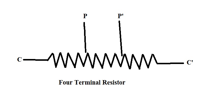
Low Resistance Standard: Low Resistance has value less than 1 ohm. Low resistance standard are Four Terminal Type. They are provided with two current terminals C and C’ & two potential terminals P and P’ as shown in figure. While in two terminal resistor only two current terminals C and C’ are provided.
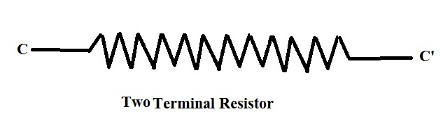
In two terminal resistor, the resistance measured between the two terminals C and C’ = V/I which also include the Contact Resistance of the Connecting Leads to terminals C and C’. The value of contact resistance is normally 0.001 ohm so if the value of resistor is 1 ohm then measured resistance in two terminal resistor = 1+0.001 = 1.001. Therefore the percentage error in the measurement = (0.001/1)*100 = 1%.
Now suppose the value of standard resistance is 0.1 ohm the percentage error will be (0.001 / 0.1)*100 = 10%. Therefore error is increasing because of Contact resistance of connecting leads as we are measuring the low resistance.
In Four Terminal Resistor, Voltage = Between the potential terminals P and P’ which are located in the middle portion of the Resistor.
The value of Resistance between the potential terminals P and P’ is called nominal Resistance. As P and P’ are located in the middle portion of the Resistor hence effect of Contact resistance of the connecting lead is ruled out. Also the current distribution in the middle part of Resistor is uniform therefore it gives a correct value of resistance.
This principle is used in the measurement of contact resistance in the joints between Circuit Breaker and conducting Bus bar, Current Transformer and connection bus etc. If you want to get detail of Measurement of Contact Resistance Measurement by four terminal method, follow me.
Effect of Frequency on Resistor: A Resistor may be represented by an equivalent circuit as shown below.
This equivalent circuit is valid for low and Medium frequencies. This circuit shows and Inductance L in series with D.C Resistance R and the combination shunted by Capacitance C. Let Z be the equivalent impedance at angular frequency ω rad/sec.
So, Z = (1/jωC)(R+jωL) / {R+jωL+(1/jωC)}
= [R+jω(L-ω2L2C-CR2)] / (1+ω2C2R2-2ω2LC+ω4L2C2)
For a Resistor, L and C are very small, hence ω4L2C2~0
Z = [R+jω{L(1-ω2LC)-CR2} / [1+ω2C(CR2-2L)]
Writing the Real and Imaginary parts, we get
Effective Resistance Reff = R/ [1+ω2C(CR2-2L)]
Effective Reactance Xeff = ω{L(1-ω2LC)-CR2} / [1+ω2C(CR2-2L)]
As Xeff is very small, therefore ω2LC may be dropped.
Xeff = ω{L-CR2} / [1+ω2C(CR2 _ 2L)]
Therefore, the effective Inductance,
So, Leff = {L-CR2} / [1+ω2C(CR2 – 2L)]
The effective Inductance is also called Residual Inductance. The effect of Residual Inductance in a Resistor may be expressed by Phase Defect Angle Ø by which current lags the applied voltage.
tanØ = Xeff/ Reff
= ω (L/R-CR)
The characteristics of Resistor is also expressed in terms of Time Constant Ƭ,
Ƭ = Leff / Reff
= L/R – CR
Therefore, it is clear that time constant of resistor may either be positive or negative depending upon whether L/R is greater than CR or not. If L/R is greater than CR then Ƭ is positive. This is the case for small resistor (1 to 10 ohm) in which Inductance dominates over Capacitance. For higher value of resistance (above 1000 ohm) capacitance predominates over Inductance and hence Ƭ is negative for Higher Value Resistor. The time constant of a Resistor is an indicator of its performance at higher frequencies and its value ranges from 0.5 to 1 micro seconds.
For D.C Resistance to be equal to effective Resistance Reff, R = Reff
So, CR2 = 2L…………..For R = Reff
If Resistance to show no inductive effect then Xeff = 0
Which means L = CR2
For Resistor, Inductance should be as low as possible, therefore L = CR2 and hence in that case D.C value of resistance will be equal to A.C value. Effective Resistance for zero Inductance will then be
Reff = R / [1- ω2LC]
Also,as R2 = L/C, hence for small Resistor, it should be designed so that Inductance is very low and Capacitance is high.
Thanks bro this is very informational post