Short Circuit Test and Open Circuit Test are two important tests which are carried out on a Transformer to determine its equivalent circuit parameters, Voltage Regulation and Efficiency.
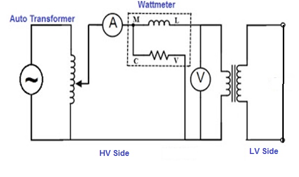 |
| Transformer Short Circuit Test |
Short Circuit Test of Transformer is performed on HV side and the supply voltage is so adjusted that rated current flows through the shorted secondary. As rated current is flowing through the shorted secondary that means that rated current will also flow in the primary because of Transformer action.
The supply voltage required for the flow of rated current in the shorted secondary is around 2-12% of rated voltage. Thus the supply voltage i.e. primary voltage is very less which in turn means that core losses during short circuit test will be negligible (as core loss is directly proportional to the square of primary voltage.).
Thus short circuit test gives us information of Ohmic loss of Transformer and the power measured by the Wattmeter is Ohmic loss. An equivalent circuit of the Short Circuit Test referred to secondary side is shown in figure below. Mind that shunt branch in the equivalent circuit is not shown as the core loss taking place during Transformer Short Circuit Test is negligible.

Let us assume that,
Vsc, Iscand Psc be the Voltage, Current and Power measured by the Voltmeter, Ammeter and Wattmeter respectively.
Therefore from the equivalent circuit diagram,
Equivalent leakage impedance referred to HV side,
ZeH = (R1+R2) + j(X1+X2)
= Vsc / Isc
But Equivalent Resistance referred to HV side,
ReH = R1+R2
= Psc / Isc2
Hence Equivalent Leakage Reactance referred to HV side,
XeH = (X1+X2) ![]()
But in case leakage impedance parameters for both primary and secondary side is required then usually,
R1 = R2 = ReH / 2
and X1 = X2 = XeH / 2 referred to same side is taken.