DC Motor speed control means to have full control on the speed of DC Motor. The variation in speed of DC Motor because of variation in load is not the speed control. Therefore intentional variation in speed of DC Motor is called Speed Control.
As we know that for a DC Motor having armature resistance Ra, rotating at some speed ωm,
Vt = Ea + IaRa where Ea = Back EMF, Ia = Armature current and Vt = Supply Voltage
But Ea = KaØωm where Ka = constant = PZ/2πa so,
KaØωm = Vt – IaRa
Therefore, ωm = Speed = (Vt – IaRa) /KaØ ………………………………(1)
From equation (1), it is clear that speed of a DC Motor can be controlled by the following methods:
- By varying the Armature circuit resistance
- By changing the field flux
- By varying the armature terminal voltage i.e. supply voltage.
We will discuss the first method of speed control i.e. by changing the Armature circuit resistance for DC Shunt Motor in this post.
Speed Control by Varying the Armature Circuit Resistance:
This method is called Armature Circuit Resistance Control method. In this method intentionally an external resistance is inserted in the Armature circuit of DC Motor. As an external resistance is added, hence there will be power loss in this resistance due to which the speed of DC motor will be less than its Name Plate speed or base speed.
Power input = Loss in External Resistance + Power Output of Motor, neglecting Motor losses.
So output power of DC Motor will reduce. Therefore, by Armature Circuit Resistance Control method only speed below base speed can be obtained.
Speed Control of DC Shunt Motor by Armature Circuit Resistance Control Method:
The connection diagram for speed control of DC Shunt Motor using Armature Circuit Resistance Control method is shown in figure below. As shown in figure an External variable Resistance Rg is connected in series with the Armature circuit, called Controller.

Assuming a constant Torque drive, the torque requirement of the drive will be constant. But Te = KaØIa so DC Shunt Motor will take constant armature current Ia to meet the constant torque requirement from the supply main as field flux Ø remain constant.
Therefore Power delivered by the supply main to the DC Shunt Motor = VtIa
But,
Power Delivered by Supply = I2(Rg+Ra) Loss + Output Power of DC Shunt Motor
VtIa = I2(Rg+Ra) +Pmo where Pmo = Motor Output
So, Pmo = VtIa – I2(Rg+Ra)
But Pmo = Teωm
So, ωm = [VtIa – I2(Rg+Ra)] / Te ……………………..(2)
If we assume that no external series resistance has been connected to armature circuit and operating speed of DC Motor is ωm0 then Rg = 0 and speed = ωm0
Therefore from equation (2),
ωm0 = (VtIa – I2Ra) / Te ……………………………………(3)
From equation (2) and (3),
ωm/ ωm0 = [VtIa – I2(Rg+Ra)] / (VtIa – I2Ra) <1
So, ωm < ωm0
Thus it is clear that speed of DC Shunt Motor reduces. As Rg is variable Resistor hence by changing this Resistance Rg we can have full control of speed of DC Shunt Motor. It is also clear that as we increase the value of External Series Resistor Rg, ohmic loss in this Rg will increase and hence the output of DC Motor will reduce which in turn will result in decreased speed.
It shall also be noted that as we increase the value of Rg, the efficiency of DC Shunt Motor will reduce as the output power of DC Motor is reducing.
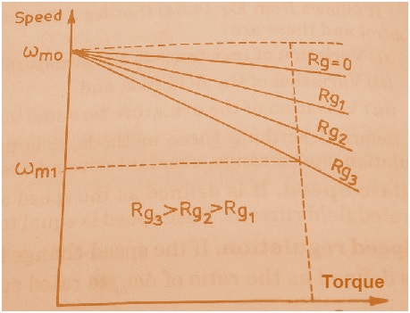
Speed Torque Characteristics of DC Shunt Motor for Different Value of Rg:
Assuming the no load speed of DC Shunt Motor = ω0 and operating speed at a given Torque Te = ωm1 then
So from equation (2) it is clear that we increase the value of External Series Resistance Rg, operating speed of DC Shunt Motor will decrease proportionally as shown in figure below.
Speed Control of DC Series Motor by Armature Circuit Resistance Control Method:
I will discuss this method for DC Series Motor by conventional way as you will find in most of the books but you can proceed in the same way as discussed for DC Shunt Motor.
The connection diagram for speed control of DC Series Motor by Armature Circuit Resistance Control Method is shown below.
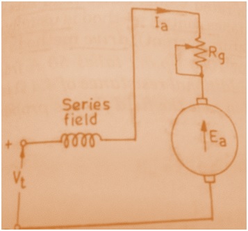
Thus the speed of DC Series Motor reduces by adding a Series External resistance Rg.
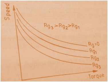
Speed Torque Characteristics of DC Series Motor for Different Value of Rg:
As we know that,
Te = KaØIa
But Ø = CIa
Hence, Te = KaCIa2
So from equation (3) it is clear that we increase the value of External Series Resistance Rg, operating speed of DC Series Motor will decrease as shown in figure below.
Hope you enjoyed this post. Your suggestion and feedback is very important to me. Thank you!
Awesome post.