What is SATACOM?
STATCOM or Static Synchronous Compensator is a power electronic device using force commutated devices like IGBT, GTO etc. to control the reactive power flow through a power network and thereby increasing the stability of power network. STATCOM is a shunt device i.e. it is connected in shunt with the line. A Static Synchronous Compensator (STATCOM) is also known as a Static Synchronous Condenser (STATCON). It is a member of the Flexible AC Transmission System (FACTS) family of devices.
The terms Synchronous in STATCOM mean that it can either absorb or generate reactive power in synchronization with the demand to stabilize the voltage of the power network.
Working Principle of STATCOM:
To understand the working principle of STATCOM, we will first have a look at the reactive power transfer equation. Let us consider two sources V1 and V2 are connected through an impedance Z = Ra + jX as shown in figure below.
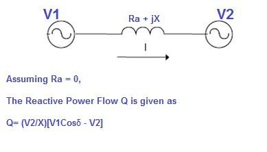
In the above reactive power flow equation, angle δ is the angle between V1 and V2. Thus if we maintain angle δ = 0 then Reactive power flow will become
Q = (V2/X)[V1-V2]
and active power flow will become
P = V1V2Sinδ / X =0
To summarize, we can say that if the angle between V1 and V2 is zero, the flow of active power becomes zero and the flow of reactive power depends on (V1 – V2). Thus for flow of reactive power there are two possibilities.
1) If the magnitude of V1 is more than V2, then reactive power will flow from source V1 to V2.
2) If the magnitude of V2 is more than V1, reactive power will flow from source V2 to V1.
This principle is used in STATCOM for reactive power control. Now we will discuss about the design of STATCOM for better correlation of working principle and design.
You may like to read Reactive Power and Voltage Control of a Transmission Line
Design of STATCOM:
STATCOM has the following components:
1) A Voltage Source Converter, VSC
The voltage-source converter is used to convert the DC input voltage to an AC output voltage. Two of the common VSC types are as below.
a) Square-wave Inverters using Gate Turn-Off Thyristors: In this type of VSC, output AC voltage is controlled by changing the DC capacitor input voltage, as the fundamental component of the converter output voltage is proportional to the DC voltage.
b) PWM Inverters using Insulated Gate Bipolar Transistors (IGBT): It uses Pulse Width Modulation (PWM) technique to create a sinusoidal waveform from a DC voltage source with a typical chopping frequency of a few kHz. In contrast to the GTO-based type, the IGBT-based VSC utilizes a fixed DC voltage and varies its output AC voltage by changing the modulation index of the PWM modulator.
2) DC Capacitor
DC Capacitor is used to supply constant DC voltage to the voltage source converter, VSC.
3) Inductive Reactance
A Transformer is connected between the output of VSC and Power System. Transformer basically acts as a coupling medium. In addition, Tranformer neutralize harmonics contained in the square waves produced by VSC.
4) Harmonic Filter
Harmonic Filter attenuates the harmonics and other high frequency components due to the VSC.
A simplified diagram along with equivalent electrical circuit of STATCOM is shown in figure below.

Now we will understand how the STATCOM works though we have discussed the basic operating principle of STATCOM. As can be seen from the figure above, source V1 represents the output voltage of the STATCOM. In case of reactive power demand increases in the power system, STATCOM increases its output voltage V1 while maintain the phase difference between V1 and V2 to zero (it shall be noted here that there will always exists small phase angle between V1 and V2 to cater for the leakage impedance drop in the interconnecting Transformer ). As V1 > V2, reactive power will flow from STATCOM to the power system. Thus STATCOM, supplies reactive power and acts as reactive power generator.
Again, if the voltage of power system increase due to load throw off, STATCOM will reduce its output voltage V1 and therefore will absorb reactive power to stabilize the voltage to normal value.
The above mode of operation of STATCOM is called Voltage Regulation Mode.
But as we know every equipment has got their own limitations, so STATCOM must also have some limitation of supplying or absorbing reactive power. Yes, there exists a limitation and this limitation is imposed by the current carrying capacity of force commutated devices like IGBT, GTO etc. Therefore, if the operation of STATCOM reaches their limitation, it does not further increases or decreases its output voltage V1 rather it supplies or absorbs fixed reactive power equal to its limiting value at a fixed voltage and current and acts like constant current source. This mode of operation of STATCOM is called VAR Control Mode.
Thus form the above discussion, the operation of STATCOM can be classified into two modes:
1) Voltage Regulation Mode
2) VAR Control Mode
The figure below well explains the above two modes of operation of STATCOM.
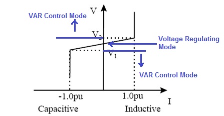
The figure above is the Voltage Current Characteristics of STATCOM. As can be seen, voltage regulation capability of STATCOM is from V1 (in lower side) to V2 in upper side of power system. If the voltage of power system goes below V1 or above V2, STATCOM acts in VAR Control mode. Here V1 and V2 are just taken for example, it should not be confused with the V1 (used for output voltage of STATCOM) and V2 (Voltage of power system) used in the discussion above.
Voltage stability is one of the biggest problems in power systems. Engineers and researchers are trying to consolidate a definition regarding to voltage stability, besides proposing techniques and methodologies for their analysis. Most of these techniques are based on the search of the point in which the system’s Jacobian becomes singular, this point is referred as the point of voltage collapse or maximum load ability point. (we will discuss point of voltage collapse in next post) The series and shunt compensation are able to increase the maximum transfer capabilities of power network .Concerning to voltage stability, such compensation has the purpose of injecting reactive power to maintain the voltage magnitude in the nodes close to the nominal values, besides, to reduce line currents and therefore the total system losses. Today due the development in the power electronics devices, the voltage magnitude in some node of the system can be adjusted through sophisticated and versatile devices named FACTS. One of them is the static synchronous compensator (STATCOM).
Usually a STATCOM is installed to support electrical networks that have a poor power factor and often poor voltage regulation. The most common use of STATCOM is for voltage stability. A STATCOM is a voltage source converter (VSC) based device, with the voltage source behind a reactor. The voltage source is created from a DC capacitor and therefore a STATCOM has very little active power capability. However, its active power capability can be increased if a suitable energy storage device is connected across the DC capacitor.
good information on STATCOM
So much helpful. I have been looking these kinds of information for few months. Thanks a lot.
Thank you so much for providing such a information which is very helpfuland easy way to understand
Really worth and clear explanation
Really clear cut explainatn.
Thank you Pawan!
Explanation was better than book.. Easy to understand! Thank you.. Keep posting more!
Anyone have complete circuit diagram of power factor improvement with statcom?
This is very good information to given STATCOM working principle
Thank you
Thank you. Kindly share the post.
you are best. thank you
Kindly share if you like it.
Thanks about rich info
Short information but simple and fully understandable. It is great.
Thank you
Very nice article with clear and simple explanation
very nice presentation,
The article presented on the subject STATCOM is very informative especially for electrical engineers that prepares the T/L design for line integrity protection. Thank you.
Good job mate. I was looking for
1. PV-STATCOM
2. Comparision between PV STATCOM and STATCOM
Excellent explanation 🙂
Thank you! Please keep visiting and sharing.
I want more details on coupling transformer.
Please mail me
Simple, effective and easy-to-comprehend. Thank you.
Thank you very much! Kindly share if you like the post
Thank you very much
Wonderful explanation on STATCOM. A whole book of information very quickly.
Thank you again.
I have searched STATCOM theory for several days and this post is the clearest one. I finally understand the basic operation principle now. Thank you very very much!
Thank you very much for this simple way of explanation . I have been looking for the definition and usages of STATCOM and got cleared now. keep posting such useful article related to Power Systems.
This is enlightening and useful.