What is Swing Equation?
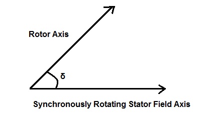
The Swing Equation of generator describes the relative motion between the rotor axis and the synchronously rotating stator filed axis with respect to time. This equation is very helpful in analyzing the stability of connected machines (machine here means generator).
Derivation of Swing Equation:
As we know that in a synchronous generator the speed of rotor axis and stator filed axis is equal to synchronous speed (N = 120f/P) during normal operating condition. This simply means that the relative speed between rotor axis and stator field axis is zero. Thus a constant angle δ is maintained between the rotor field axis and stator filed axis under normal operating condition. This angle δ is known as Load Angle or Torque Angle.

The value of load angle depends on the loading of machine. The more is the load, the more will be the load angle δ as suggested by the power equation
P = EfVtSinδ / Xs
where Ef = No Load Excitation Voltage
Vt = Generator Terminal Voltage
Xs = Synchronous Impedance
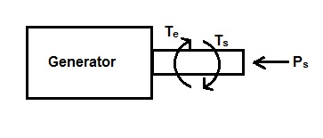
Also, during steady state operation of generator the value of electromagnetic torque Te is equal to shaft torque Ts. Since electromagnetic torque Te and load torque Ts act in opposite direction, there is no net torque on the rotor. This is the reason; rotor rotates at constant angular velocity during steady state operation of generator.

But when there is a sudden change in the loading of machine i.e. if some load is added or removed from the rotor shaft, the rotor will accelerate or decelerate with respect to the synchronously rotating stator field. Suppose steam input to the generator is suddenly increased, under this condition the rotor will accelerate as the electromagnetic torque Te will remain almost constant during transient period but shaft torque Ts has been increased. Thus a relative motion will set in between the rotor and stator field axis. Since generator terminals are assumed to be connected to Grid, the stator filed axis can be taken as reference for study of relative motion. Due to this relative motion, the load angle δs will vary with time and can be written as
δs = ωrt + δ ………………(1)
where δs is the angle between the reference stator field axis and rotor axis at any time t and δ is the load angle just before the rotor disturbance.
where wr is the relative angular speed between the rotor axis and stator filed axis.
Also, Ts – Te = Ta
where Ta = Net Accelerating Torque
Since a synchronous machine rotates at constant angular speed, hence the above torque can be replaced by power for analysis. Hence Te is replaced by electromagnetic power Pe and Ts by shaft power Ps. Thus the rotor accelerating power Pa can be written as,
Ps – Pe = Pa
But as per mechanics, power = Torque x Angular Speed
Therefore,
Accelerating power Pa = Taω ………(2)
Since, Torque = Inertia (I) x Angular Acceleration (α)
Therefore from (2),
Pa = Iωα ………………(3)
Let, M = Iω
But Iω is the angular momentum, hence M is called the angular momentum of generator rotor. Therefore from (3),
Rotor / Shaft Accelerating Power Pa = Mα …….(4)
It should be noted here that while applying mechanics for the analysis of relative motion between rotor axis and stator axis, the unit of angular speed w should be considered in mechanical radian per second. But since we can convert this mechanical radian per second into electrical radian per second by suing
Electrical radian or degree = Mechanical Radian or degree x No. of Pole Pairs
Please read “Concept of Electrical and Mechanical Angles & Synchronous Speed” for getting clear understanding of conversion of mechanical angle and electrical angle & their conversion.
But the angular position of rotor w.r.t is described by (1),
δs = ωrt + δ
Differentiating both side w.r.t time,
dδs / dt = ωr +dδ/dt
Again differentiating w.r.t time,
d2δs / dt2 = d2δ/dt2
But d2δs / dt2 = angular acceleration of rotor i.e. α
Hence from (4),
Pa = Mα = Md2δ/dt2
But Pa = Ps – Pe
⇒ Ps – Pe = Md2δ/dt2 …………..(5)
The above equation is known as the Swing Equation.
Different forms of Swing Equation:
The above swing equation can be expressed in different forms. Before we express this equation in terms of other parameters, it is imperative to discuss the related terms i.e. Inertia Constant M and H.
Since angular momentum M of machine = Iω, therefore M will remain practically constant as the machine operates at constant synchronous speed and hence constant angular speed. This constant M is called the Inertia Constant of machine. The value of M depends on the size of machine. The larger the size, the more will be inertia constant M.
H is another frequently used constant in stability analysis. This constant is defined as the ratio of kinetic energy of machine to the rated MVA machine capacity. Thus
H = Machine Kinetic Energy / Rated MVA Capacity
This constant H is also known as inertia constant. The relationship between M and H can be derived as below.
Let G = Rated MVA capacity of Machine
f = system frequency
As per definition of H,
H = Kinetic Energy / G
But,
Kinetic Energy of Machine = Mω/2
= [M x (2πf)]/2
= Mπf
Therefore,
H = Mπf / G
⇒ M = GH / πf Mega Joule Second / Radian
= GH / 180f Mega Joule Second / electrical radian
Thus from (5) Swing Equation can also be written as,
Ps – Pe = (GH/180f) x d2δ/dt2 ……(6)
In terms of per unit system, the Swing Equation becomes
(Ps – Pe)pu = (H/180f) x d2δ/dt2
Notice that the above equation has been obtained by dividing (6) by G. This is done to convert into per unit system.