Ungrounded System is one where the neutral is not connected to earth. Thus, neutral of ungrounded system is isolated. Arcing Ground is an electrical phenomenon in which the voltage of faulty phase fluctuates due to capacitive charging current. This arcing ground phenomenon is prevalent in three phase ungrounded neutral system. Don’t worry I will explain this in detail.
We know that, a transmission line has shunt capacitance associated. Due to this shunt capacitance, a charging current flows from line to ground under normal operating condition. Let us consider a three phase ungrounded neutral system as shown in figure below.
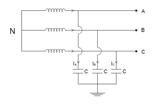
As shown in figure above, shunt capacitance for each line is C. IA, IB and IC are the charging current corresponding to three phases A, B and C. Under normal operating condition, these charging currents will lead their corresponding phase voltage by 90°. Thus if we draw the phasor for this, then it will look like below.
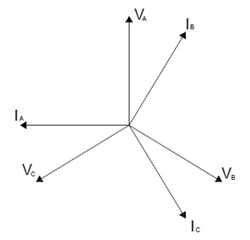
Carefully observe that IA, IB and IC are leading phase voltage VA, VB and VC by an angle 90°. But the angles between the three charging currents are maintained 120°. Thus we can say that, the charging currents are balanced and therefore,
IA+IB+IC = 0
Thus there will be no flow of current through the neutral. Hence the potential of neutral will be maintained at the ground potential.
Let us now consider a fault condition. Suppose a single line to ground fault takes place in C phase as shown in figure below.
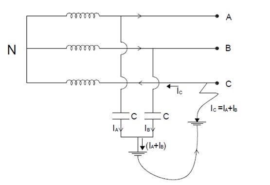
The fault current this case will complete its circuit as shown in figure above. Fault current IC will be equal to the vector some of IA and IB. Therefore,
IC = IA + IB
Mind here that, IC in C phase will flow toward the neutral. Therefore we can say that, phase voltage of C phase has reversed its direction. This in turn means that, the voltage of neutral point has shifted from ground potential to phase voltage.
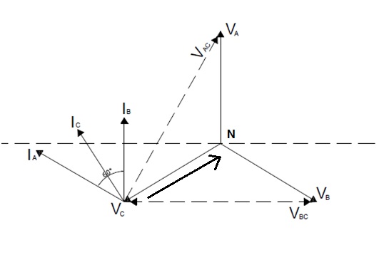
Because of this shifting of neutral voltage, the voltage of healthy phase will become equal to the line voltage. This can be well understood by applying Kirchhof’s voltage law in the current loop of phase A.
(VC – VN) + (VN-VA) + (VA-VC) = 0
So,
(VA-VN) = (VC – VN) + (VA – VC)
= -VC + (VA – 0)
= -VC + VA
= VA – VC = Line Voltage = VAC
But VA – VN = Phase Voltage of A phase. Thus we observe that, the voltage of healthy phase rises to line voltage i.e. √3Vph. Due to this raised voltage of healthy phases, charging currents will increase.
IA = √3Vph / XC
and IB = √3Vph / XC
where XC is capacitive reactance.
These charging currents will now lead with their respective voltages by 90° as shown in phasor diagram above. But notice that, this time the voltage is line voltage.
Therefore the fault current will be,
IC = IA + IB (vector sum, please correlate with phasor diagram)
= 3Vph/XC
From the above expression of fault current, it is clear that charging current in faulted phase is three times that of the normal charging current. Due to this heavy arcing will take place in the faulted phase. This phenomenon of arcing is known as Arcing Ground. Peterson coil is used for the elimination of arcing ground.
very well explained
No
Still have to explain why the conductor moving when arcing ground happened
I didn’t understand “conductor moving when arcing ground happened”. It will be great if you can add some value on this.
Very much helpful.
Thank you!Please share the post.
Could you also explain why the arcing continues to happen ? Many posts havent been able to address it clearly using mathematics! Thanks