The concept of system grounding is extremely important, as it affects the susceptibility of the system to voltage transients, determines the types of loads the system can accommodate, and helps to determine the system protection requirements.
The system grounding arrangement is determined by the grounding of the power source. For commercial and industrial systems, the types of power sources generally fall into four broad categories:
Utility Service – The system grounding is usually determined by the secondary winding configuration of the upstream utility substation transformer.
Generator – The system grounding is determined by the stator winding configuration.
Transformer– The system grounding on the system fed by the transformer is determined by the transformer secondary winding configuration.
Neutral grounding is generally of three types:
- Solid Grounding
- Resistance Grounding
- Reactance Grounding
Each of the grounding method serves a specific purpose and based on the suitability of our need, we use any one of the grounding method.
Solidly Grounded Systems:
The solidly grounded system is the most common system arrangement, and one of the most used. The most commonly used configuration is the solidly grounded star, because it support single-phase phase to neutral loads. In this type of grounding method, the star point is directly connected to the ground.
The figure below, shows the relationship between the phase and line voltage for Solidly Grounded System.

It can be seen from the above figure that the system voltage with respect to ground is fixed by the phase-to-neutral winding voltage. It means that the line-to-ground insulation level of equipment need only be as large as the phase-to-neutral voltage, which is 57.7% (100/1.732 = 57.7 %) of the phase-to-phase voltage. It also means that the system is less susceptible to phase-to-ground voltage transients. This is very important benefit of Solidly Ground System.
A common characteristic of solidly-grounded system is that a short circuit to ground will cause a large amount of short circuit current to flow. This condition is known as a ground fault. As can be seen from figure below the voltage on the faulted phase is depressed, and large current flows in the faulted phase since the phase and fault impedance are small.
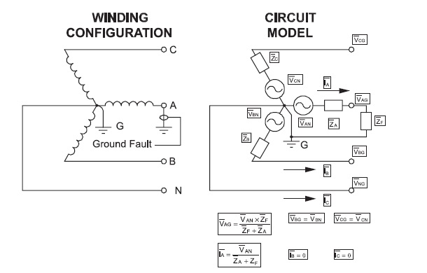
The voltage and current on the other two phases are not affected. Thus a solidly grounded system supports a large ground fault current. Statistically, 90-95% of all system short-circuits are ground faults.
The occurrence of a ground fault on a solidly grounded system necessitates the removal of the fault as quickly as possible. This is the major disadvantage of the solidly-grounded system as compared to other types of system grounding.
A solidly-grounded system is very effective at reducing the possibility of line-to-ground voltage transients. However, to do this the system must be effectively grounded. One measure of the effectiveness of the system grounding is the ratio of the available ground-fault current to the available three-phase fault current. For effectively grounded systems this ratio is usually at least 60%.
To summarize,
The solidly grounded system is the most popular, is required where single-phase phase-to-neutral loads must be supplied, and has the most stable phase-to-ground voltage characteristics. However, the large ground fault current is a disadvantage and can be hindrance to system reliability.
Resistance Grounded Systems:
In Resistance Grounding method, the neutral point is connected to the ground by using a Resistor. The resistor is sized to allow 1-10 A to flow continuously if a ground fault occurs.

The resistor is sized to be less than or equal to the magnitude of the system charging capacitance to ground. If the resistor is thus sized, the high-resistance grounded system is usually not susceptible to the large transient overvoltages that an ungrounded system can experience.
If no ground fault current is present, the phasor diagram for the system is the same as for a solidly grounded system. However, if a ground fault occurs on one phase the system response is as shown in figure below. As can be seen from figure below, the ground fault current is limited by the grounding resistor.
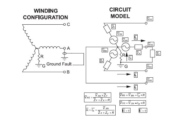
If the approximation is made that ZA (impedance of winding) and ZF (Fault impedance) are very small compared to the ground resistor resistance value R, then the ground fault current is approximately equal to the phase-to-neutral voltage of the faulted phase divided by R. The faulted phase voltage to ground in that case would be zero and the unfaulted phase voltages to ground would be 173% of their values without a ground fault present.
The ground fault current is not large enough to force its removal by taking the system off-line. Therefore, the high resistance grounded system has the same operational advantage in this respect as the ungrounded system.
Reactance Grounding:
A Reactance Grounded system is one in which the neutral point is grounded through an impedance which is highly inductive. Reactance Grounding lies between the effective grounding and Resonant Grounding (will be discussed in next post). Reactance is provided to keep the fault current within safe limit. This method of grounding is used where the charging current is high like in capacitor bank, line reactors used for voltage control of transmission line etc.
Useful information particularly electrical fundamentals. Information on electrical system
I would rather say this has to be explained in terms of how does neutral system affects the stability of the power system. Wld u pls explain that. Other than in terms of its effect on the introduction of harmonics and stability of generator and its synchronize.