For better understanding of advantages and disadvantages of Short-pitched winding, we shall first understand the meaning of short-pitched coil and full-pitched coil. It will take some 10 minutes of your precious time to go through the write-up but it will really help you.
Full Pitch Coil:
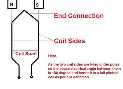
A full pitched coil is defined as the coil whose two coil sides are 180 electrical degree apart. As the Pole Pitch, which is defined as the space electrical angle between two consecutive poles is 180 degree, therefore in an alternate manner we can also say that a Full Pitch Coil has its two coil sides one pole pitch apart. This can be seen in the figure below.
If it happens that the two coil sides are not lying under the pole, then obviously the space electrical angle between the coil sides will not be 180 degree rather it will be less than 180 degree as shown in figure below.
Thus we can define a Short Pitch Coil as the coil having the coil span (Coil Span is defined as the space angle between the two coil sides of a coil) less than 180 degree. A short pitched coil is also known as Chorded Coil.
Chording Angle ξ is defined as the angle by which the coil span departs from a pole pitch i.e. 180 degree.
Thus, Chording Angle ξ = 180° – Coil Span
If Chording Angle ξ is zero then it is a full pitch coil.
So we are now familiar with the Full Pitched Coil and Short Pitched Coil. But is it sufficient to judge the advantage and disadvantage of Short Pitched Coil?
No, this much information is not enough to have an idea of advantage and disadvantage of short pitch coil. But if we can see the effect of the above two types of winding on Generated EMF then we could have some idea. So we will just see the effect of short pitching on the generated EMF.
The rms value of EMF Generated in a Full Pitched Winding of N turns
E = 1.141 πfNØ
Whereas the rms value of EMF Generated in a Short Pitched Winding of N turns
E = 1.141 πfNØCos(ξ/2)
Here the term Cos(ξ/2) is called Pitch Factor.
Kp= Pitch Factor = Cos(ξ/2)
Thus it can be seen that a Short Pitched Coil reduces the output voltage by a factor Kp i.e. Cos(ξ/2). Thus is the disadvantage of Short Pitch Coil.
- Short Pitching reduces the amount of copper needed for End Connection when compared with Full Pitched Coil as can be observed from the figure above.
- They improve the waveform of generated EMF i.e. generated EMF can be made to approximate to a sine wave more easily and the distorting harmonics can be reduced or totally eliminated. How?
- Suppose you want to eliminate 3rd harmonic from the Generated EMF. So what we do is that we will select Chording Angle ξ in such a manner that Cos(nξ/2) becomes zero i.e. Pitch Factor becomes zero for 3rd harmonics only. Mind here that Pitch Factor for nth harmonic is Cos(nξ/2).
Therefore, Cos(nξ/2) = 0
For eliminating 3rdharmonic from Generated EMF,
Cos(3ξ/2) = 0
3ξ/2 = π/2
ξ = π/3 = 60°
- Due to the elimination of high frequency harmonics, eddy current and hysteresis losses are reduced, thereby increasing the efficiency.
Disadvantages of Short Pitch Coil:
The disadvantages of using short-pitch winding is that, the total voltage around the coils is somewhat reduced. In order to compensate for this reduction in Generated EMF, more number of turns and therefore more copper is required.
Thank you!


Very nice explanation.
Very nice description regarding full pitch and short pitch winding . I got clear idea regarding this topic
The best blog for electrical engineering till date…hats off author… the clarity is what I love.
thank you akanksh
Superbly Explain…… Tomorrow is my exam and really today I understand this. Perfectly after 8 years of engineering……
Nice explations
I got full information of this sections. Thanking for ur sharing in this information
May I correct this “E = 1.141 πfNØ” to “E = 4.44 fNØ” for E.M.F of rms per phase.
Thank you very much but both are same since 1.414xπ = 4.44
why when both sides of coil lies under similar polarity the induced EMF doesn’t cancel each other .