When single core cable is used for AC power transmission, the current flowing through the core of cable set up pulsating magnetic field in its surrounding. This magnetic field links with the cable sheath and hence as per the Faraday’s Law an induced voltage is developed in the sheath. This induced voltage in certain conditions causes a circulating current in the cable sheath. This circulating current in cable sheath leads to sheath loss and hence cable heating. Thus apart from core loss (I2R loss in cable core), sheath loss also take place.
The induced sheath currents in cable are of two types:
- Sheath Eddy Current: Sheath Eddy Currents are the induced current flowing over the entire sheath of the same cable. Eddy current loss in sheath take place when sheath of two cable are not connected or connected at a single point.
- Sheath Circuit Current: Sheath Circuit Current is the induced current flowing in a circuit composed of sheath of two different sheaths of adjacent cables. Figure below shows two single core cables whose sheaths are electrically connected at both ends. Such connection of cable sheaths is called cable bonding or bonding of cables.
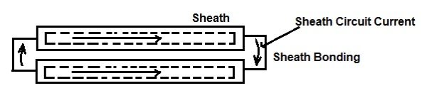
It can be seen from the above figure that induced current is flowing sheath of one cable to sheath of another adjacent cable via bonding. Thus for sheath circuit current to flow, it is necessary that sheaths of cables must be electrically connected at both ends.
Corresponding to above two types of circulating current, there must be two different types of sheath loss. Yes, one is loss due to eddy current and another one is loss due to sheath circuit current.
Sheath Loss due to Sheath Eddy Current:
Sheath Loss due to Sheath Eddy Current is given as
Psh_eddy = I2[(3w2/Rsh)(rm/d)2x10-8] watt / cm /phase
where
I = Current flowing in the cable core
rm = Mean Radius of Sheath
d = Spacing between the Cable cores
Rsh = Sheath Resistance
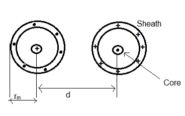
For all calculations of mean radius, inductance and mutual inductance where single core cable are used for ac power transmission, theory of overhead lines are well applicable. Figure below shows the different parameters used in the above calculation.
Sheath Loss due Sheath Circuit Current:
Sheath loss due to sheath circuit current is dependent on the effective resistance of bonded cable. Therefore it is important to understand and calculate the resistance of bonded cable. A cable may be assumed to be a transformer whose primary is represented by cable core and secondary by sheath. This transformer will obviously be loosely coupled due to cable insulation. Based on this assumption, the equivalent circuit of cable may be represented as below.
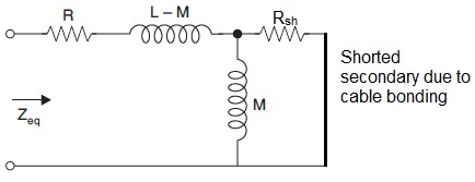
In the above equivalent circuit of cable, R, L, M and Zeq represents the cable core resistance, inductance, mutual inductance and equivalent impedance when viewed from primary terminal respectively. Shorting of secondary is due to bonding of sheaths of two cables.
Therefore,
Zeq = R + jω(L-M) + Rshx(jωM) / (Rsh + jωM)
= R + jω(L-M) + Rshx(jωM)( Rsh – jωM) / {(Rsh)2 + (ωM)2}
= R + jω(L-M) + (ωRshM)2/{(Rsh)2 + (ωM)2} + jωMRsh2 / {(Rsh)2 + (ωM)2}
= [R + ω2RshM2 / {(Rsh)2 + (ωM)2}] + jω [(L-M) + MRsh2 / {(Rsh)2 + (ωM)2}]
= [R + ω2RshM2 / {(Rsh)2 + (ωM)2}] + jω [L- M3ω2 / {(Rsh)2 + (ωM)2}]
Equating real and imaginary parts, we get the effective resistance and inductance of the bonded cable.
Reff = R + ω2RshM2 / {(Rsh)2 + (ωM)2}
Leff = L- M3ω2 / {(Rsh)2 + (ωM)2}
Thus the sheath loss due to sheath circuit current I is given as
I2Reff
= I2 [R + ω2RshM2 / {(Rsh)2 + (ωM)2}]
From the above expression of resistance and inductance, it can be seen that effective resistance of cable is increased while the inductance is decreased by bonding of cable. Due to increased effective resistance, the sheath loss will increase leading to more cable heating. Does this mean that we should avoid cable bonding? Not really, cable bonding reduces the induced voltage in the sheath during short circuit fault condition. If there were no cable bonding then the voltage in between the sheaths of cable will be high enough to cause sparking and subsequent pitting and damage of sheath.
Then the question arise, how to reduce the sheath loss due to sheath circuit current?
Well, we can reduce the sheath circuit current ‘I’ to reduce the sheath loss. To reduce sheath circuit current I, we need to reduce the induced voltage in between the sheath of two adjacent cable. For this purpose, method of cross bonding and transposition of cable is used.
Very nice information….
Thank you Deepak!
It’s so nice information 🙂
Can I ask some questions about your article?
1. Current I is an RMS value? or peak value?
2. What is the unit of Sheath Resistance? Is it related to the unit of P_sh(W/cm/phase)?
3. How can you calculate the Sheath Resistance? I used the following equation, R_s=l/(sigma*S)=1000/(3.8*10^7*pi*(r_out+r_in)(r_out-r_in)) [ohm/km], is that okay for it?
Thanks in advance
Have a nice day!