Restriking voltage is the transient voltage appearing across the breaker contacts immediately after the opening of breaker contacts. It is also called Transient Recovery Voltage (TRV).
Restriking voltage is associated with high frequency which die out quickly. Even though restriking voltage is lasts for very short duration, its importance for breaker fault clearing cannot be ignored. If the rate of rise of dielectric strength of medium is less than the restrining voltage, arc quenching will not take place and hence fault will not be interrupted. This will in turn increase the fault clearing time which is not desirable. In this post we will focus our attention to the calculation of restriking voltage with the following assumption:
- The fault does not involve any arcing i.e. the fault is solid one.
- Effect of corona and saturation is ignored. Corona and saturation of machine attenuates the voltage surge during breaker contact opening by dissipating energy.
- The current interruption is assumed to be taking place at natural current zero.
- The whole system is assumed to be lossless.
The above assumptions are considered to arrive at the maximum restriking voltage after the removal of fault by breaker contact opening. Figure below shows the simplest model of system consisting of a source connected to a bus bar. The inductance and capacitance of the system is lumped together and connected in series and parallel with the source respectively.
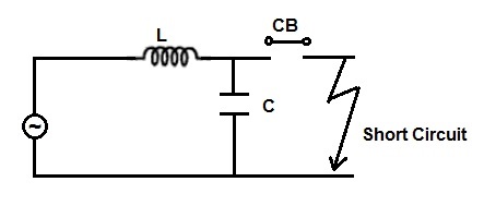
A solid fault takes place and in response to the fault, breaker contacts open to isolate the faulty network from the healthy system. We are now required to find the voltage across the breaker contacts immediately after the breaker contact opening.
The voltage across the breaker contact will be equal to the multiplication of fault current and the system impedance as seen from the CB (circuit breaker) contacts with voltage source shorted (as per thevenins’ theorem). Let us assume this voltage to be v(t). For making calculations easy, it will be a smart way to consider every parameter in laplace domain. Therefore,
V(s) = Source Voltage
I(s) = Fault Current
Z(s) = System Impedance as seen from CB contacts
Hence,
V(s) = I(s)Z(s) ………….(1)
But source voltage is VmSinωt, hence source voltage at natural current zero i.e. when breaker contact open will be Vm. Therefore V(s) = Vm /s and impedance is mainly offered by inductance, this means Z(s) = Ls
Thus from (1),
Vm/s = I(s)Z(s)
I(s) = Vm / Ls2 ………..(2)
Now let us find the Z(s). Z(s) will be parallel equivalent of inductance L and capacitance C when viewed from breaker contact. Therefore,
Z(s) = [(Ls)(1 / Cs)] / [Ls + 1/Cs]
= Ls / [Ls + 1/Cs]
= (s / C) / [s2 + 1/LC]
Now from (2),
v(s) = Voltage across breaker contact immediately after opening
= Restriking Voltage
= Transient Recovery Voltage
= I(s)Z(s)
= [(Vm/s)(1/sL) (s / C)] / [s2 + 1/LC]
= Vm [1/s – s / (s2 + 1/LC)]
Taking inverse laplace transform, we get
v(t) = Vm[1 – cosω0t] ………(3)
where ω0 = 1 / √LC and hence f0 = (1/2π√LC) where f0 is the natural frequency of oscillation.
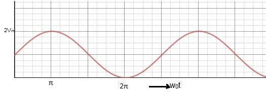
The maximum value of TRV = 2Vm when ω0t = π
t = π / ω0
= π / (1 / √LC)
= π √LC
Expression (3) is the restriking or transient recovery voltage. It can be seen from the expression that TRV is of sustained oscillating nature. But it is not true. The above expression has been arrived at by assuming some conditions which eliminates the damping effect. In real scenario, Restriking voltage die out due to damping effect of corona, arc involved in faults etc.