A Capacitor is a device which has the capability to store energy in its Electric Field. Therefore we can say that a Capacitor can store charge. There are many types of Capacitor but the most basic Capacitor is Parallel Plate Capacitor. We will consider this basic capacitor for getting idea of basic but important parameters of Capacitor.
A parallel plate Capacitor is made of two plates separated by some distance. Let’s assume that the separation between the plates is d. We apply a DC voltage across the parallel plate. What will happen then?
Obviously the charges will start to accumulate on the plate and will continue to accumulate until the potential difference between the plates becomes equal to applied Voltage V. Say charge +Q is accumulated on one plate and –Q on another plate. Then mathematically we can have
Q = CV
Here the term C is known as Capacitance.
Does the Capacitance depend upon the Voltage applied across the Capacitor?
You might answer yes. But it’s not correct. Capacitance only depends upon the physical dimension, dielectric and geometry of Capacitor. In fact the value of Capacitance for a parallel plate Capacitor is given as
C = E0ErA / d
Where E0 = Permittivity of free space.
Er = Relative permittivity of dielectric.
d = Separation between the plates.
A = Cross sectional area of plate
So, from the above it is quite clear that Capacitance depend only on dimension, dielectric and geometry.
A Capacitor finds much use in Electrical Engineering and Technology. The size of Capacitor varies from very small to large one. The application of Capacitor ranges from tiny electronic circuit to 765 kV Circuit Breaker as Grading Capacitor. Therefore, it is very much important Capacitor is in pure state but honestly speaking it is much difficult to manufacture pure Capacitor rather it have some resistance in it which causes ohmic loss. Therefore, the measurement of this loss is much needed. The question arises how do we measure this loss? The answer is simple, by measuring Dissipation Factor.
What is Dissipation Factor?
For answering this question we need to realize a real Capacitor. A Capacitor can be realized as series combination of small resistance of dielectric medium and capacitance as shown in picture below.
If we draw the phasor diagram, it will look like,
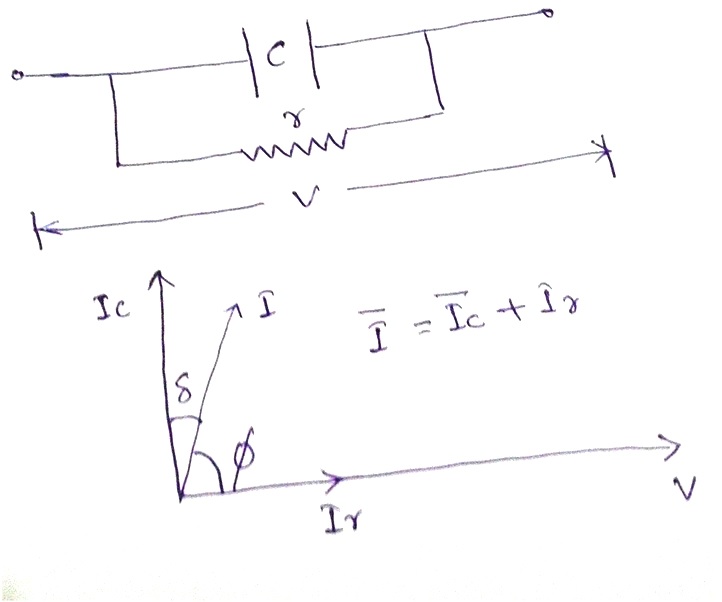
If the Capacitor had been pure then it would have taken current Ic leading by angle 90 degree but because of resistive component of dielectric, net current drawn is deviating from 90 degree by some angle δ. This angle δ is hence called Loss Angle. From the phasor diagram, it is clear that
tanδ = Ir / Ic= Capacitive leakage current / Resistive leakage current.
This tanδ is also called Dissipation Factor. Why called Dissipation Factor? Be patient, you will come to know latter in this topic.
Now, we will calculate the Power Factor of the Capacitor. If the Capacitor would have been pure then the P.F would have been Cos90 = 0 but because of some resistive component it will no more be zero rather it will be something close to zero like 0.001.
CosØ = Cos(90-δ) = Sinδ
As is angle δ is very small, hence Sinδ ~ tanδ~δ
Therefore, dielectric loss = VICosØ = VISinδ
= VIcSinδ/Cosδ
= VIctanδ
Therefore, dielectric loss is proportional to tanδ. That is why tanδ is often called Dissipation Factor too. For a good capacitor, obviously the value of tanδ should be very less as it will cause less dielectric loss.
For VIDEO TUTORIAL OF THIS TOPIC click below.
For VIDEO TUTORIAL OF THIS TOPIC click below.
In my next post, you will learn how do we measure Capacitance and Dissipation Factor. Be patient till then and follow me. Thank you
Thanks for explaining in so lucid manner. But as you said Power Factor and Tan delta are same but as i know both are different. Can you please explain?
Yes, power factor and tand delta are same but when angle delta is very small. Mind angle here is very small therefore tan delta and power factor are equal.