The application for capacitor voltage transformers, CVTs, is the same as for Inductive Voltage Transformers. The main function of a Capacitive Voltage Transformer is as follows:
- To transform currents or voltages from a usually high value to a value easy to handle for relays and instruments.
- To insulate the metering circuit from the primary high voltage system.
- To provide possibilities of standardizing the instruments and relays to a few rated currents and voltages.
Capacitive voltage transformers (CVTs) are used on higher voltage levels, starting from 66 kV and upwards. The type of the CVT is always a single-pole one, thus the connection is between phase and earth.
Construction of Capacitive Voltage Transformer:
The CVT consists of two parts, the capacitive voltage divider (CVD) with the two capacitances C1and C2 and the Electromagnetic Unit (EMU). The size of the capacitances C1 and C2 determines the voltage ratio of the CVD. The EMU contains an inductive voltage transformer, a tuning reactance and a protection against ferro-resonance.
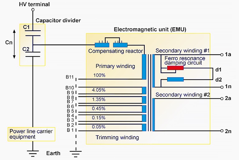
The trimming windings are used for fine tuning the output signal to correspond with the required accuracy class requirements. The compensating reactor compensates the phase angle shift caused by the capacitive voltage divider.
The capacitance C1in the voltage divider, in series with the inductance of the compensating reactor and the wound transformer, inside the electromagnetic unit EMU, constitutes a tuned resonance circuit. Unlike with the inductive type of voltage transformers, the CVTs usually have the Ferroresonance damping circuit inbuilt in the CVT itself.
As shown in figure above, secondary terminal (1a,1n), (2a,2n) etc. are used for the Protection Circuit or Metering Circuit. Typical voltage ratio for a CVT is 400 kV / 110 V which means that if a CVT is placed in a phase of 400 kV line then the secondary voltage will be 110 V.
Operating Principle:
A Capacitive Voltage transformer works on Capacitor Voltage Divider principle. For better understanding, assume a simple circuit of CVT which is connected between a line of 400 kV and Earth.

As the CVT is connected between the line and earth, therefore phase voltage (400/1.732 = 230 kV) will be applied.
Therefore,
Voltage across the Capacitor C1 = (230×C2)/(C1+C2)
Voltage across the Capacitor C2 = (230×C1)/(C1+C2)
Thus if an Electromagnetic Unit is connected across the C2 then its voltage rating will reduce. The output secondary voltage will depend on the impedance of EMU unit as below
Secondary Terminal Voltage = (Zm× Voltage across the Capacitor C2)/(Z1+Z2+Zm)
Where Zm = magnetizing Reactance of EMU unit.
Z1 = Primary impedance of EMU unit.
Z2 = Secondary impedance of EMU unit.
This is the simple working principle of a CVT.
Thank you!
please explain in details how the sec terminal voltage formula arrived.
It is already detailed. Where you have problem in understanding? Please point out so that I can help.
please explain the formula of sec terminal voltage. why z1+z2+zm?
To understand, draw equivalent circuit of Transformer. You will understand, how the formula has been arrived at.