In last post Power Swing, we discussed Power Swing and behavior of machine on Power Swing. Now we will discuss the impact of Power Swing on Distance Relaying.
We consider the two machine system connected by Transmission line of Impedance ZL as shown in figure below.
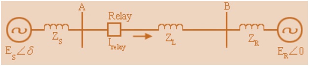
For making the calculation easy, assume ER as reference and its angle as zero. Therefore current seen by Relay located at A,
I= Volateg / Z
= (Esejδ – ER) / (Zs+ZL+ZR)
Let, Z = Zs+ZL+ZR
Now, Impedance seen by Relay,
Z = Voltage seen by Relay/Current seen by Relay
= (Esejδ– IZs)/I
= -Zs + Esejδ/I
= -Zs + Esejδ/[(Esejδ– ER) / (Zs+ZL+ZR)]
= -Zs + EsejδxZ/(Esejδ– ER) ……………………(Since Z = Zs+ZL+ZR)
= -Zs + Z/[1- (ER/ES) e-jδ]
Assume that ER/ES = K and K = 1 for simplicity then
Z = -Zs + Z/[1- e-jδ] = -Zs + Z/[1-cosδ+jsinδ]
= -Zs + (Z/2)/[sin2δ/2+jsinδcosδ] = -Zs +(Z/2sinδ/2)/[sinδ/2 + jcosδ/2]
= -Zs + (Z/2sinδ/2)( sinδ/2 – jcosδ/2)
= -Zs + (Z/2)( 1 – jcotδ/2)
Therefore,
|
Impedance seen by Relay, Z = -Zs + (Z/2)( 1 – jcotδ/2)
= (-Zs +Z/2) – j(Z/2)cotδ/2
|
From above equation of Impedance seen by Relay, if δ= 180°
Z = (-Zs +Z/2) as cotδ/2 = 0
Geometrical Interpretation:
The vector component in above equation is a constant in R – X plane. The component – j(Z/2)cotδ/2 lies on a straight line, perpendicular to line segment (-Zs +Z/2). Thus, the trajectory of the impedance measured by relay during the power swing is a straight line as shown in figure below. The angle subtended by a point in the locus on S and R end points is angle δ. For simplicity, angle of Zs, ZR and ZL are considered same.
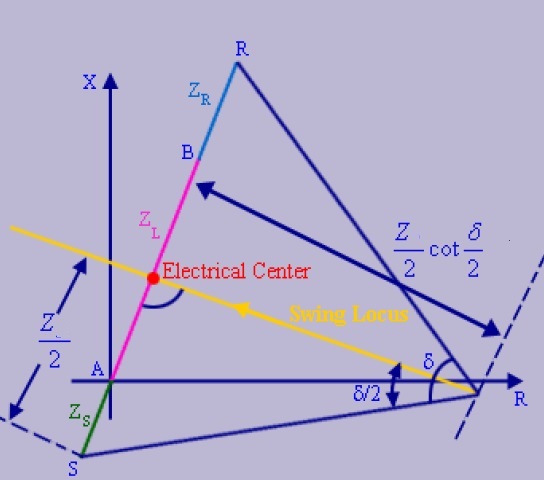
The point where the Power Swing locus intersects line AB, the angle between ES and ER is 180 degree which means both the sources are out of step. This point of intersection is called Electrical Center.
The existence of the electrical center is an indication of system instability, the two Generators being out of step. If the power swing is stable, i.e. if the post fault system is stable, then δmax will be less than (180°- δ) as in this case both the sources won’t be out of step.
Now, suppose ER/ES = K ≠1 then,
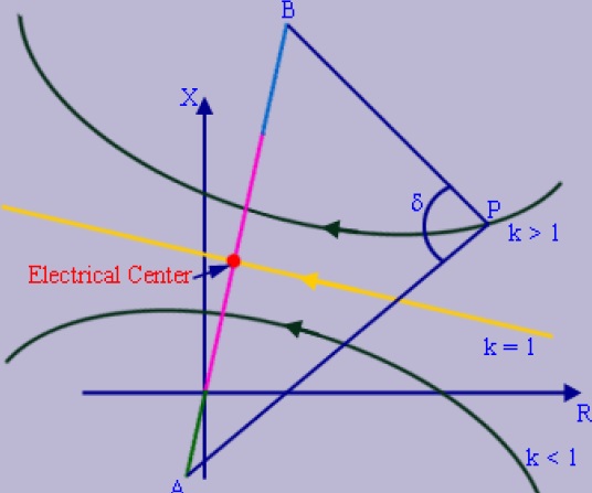
It is also clear from the above figure that the location of the Electrical Center is dependent upon the ratio ES/ER. Appearance of electrical center on a transmission line is a transient phenomenon. This is because, during unstable transient, is not stationary. As the rotor angles separate in time Electrical Center arises during out-of-step condition.
Voltage at the Point of Occurrence of Electrical Center:
The voltage profile across the transmission system at the point of occurrence of electrical center is shown in figure below.
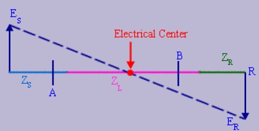
At the electrical center, the voltage is exactly zero. This
means that relays at both ends of the line perceive it as a bolted three phase fault and immediately trip the line. Thus, we can conclude that existence of Electrical Center means system instability which can introduce nuisance tripping of distance relay.
Now consider a double end- fed transmission line with three stepped distance protection scheme having Z1, Z2 and Z3 protection zones. The mho relays are used and characteristics are plotted on R-X plane as shown in figure below.

Here, Swing impedance trajectory is also overlapped on relay characteristics for a simple case of equal end voltages (i.e. k = 1) and it is perpendicular to line AB. It is clear from figure that δz1, δz2 and δz3are rotor angles when swing just enters the zone Z1, Z2 and Z3 respectively and it can be obtained from the intersection of swing trajectory with the relay characteristics as shown in figure above.
As we know that δmaxis the maximum rotor angle for stable Power Swing, hence we can conclude following from the figure:
- If, δmax< δz3 then swing will not enter the relay characteristics.
- If, δz3<δmax< δz2 swing will enter in zone Z3. If it stays in zone -3 for larger interval than its time setting, then the relay will trip the line.
- If δz2<δmax< δz1, swing will enter in both the zones Z2 and Z3. If it stays in zone-2, for a larger interval than its time setting, then the relay will trip on Z2. Typically, time setting of Z2 is less than Z3.
- If δmax> δz1, swing will enter in the zones Z1, Z2 and Z3 and operate zone-1 protection without any intentional delay.
Thank you! Please write your comment if in doubt.
Pl. explain out of step protection of generator and also explain out of step protection, loss of excitation protection on same RX plane.
Thanq sooo much for making a very complicated topic sooo simple.
“This is because, during unstable transient, is not stationary. As the rotor angles separate in time Electrical Center arises during out-of-step condition.”
this sentence is not clear
please look into it.
Thanks again
Thank you for your suggestion. I will definitely look into it to bring more clarity.
Thanks a lot for your excellent effort to explain this critical topic.
Thank you for your appreciation.
How can one know the point of origin of Power Swing in transmission network.