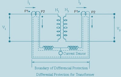
As discussed in the post “Transformer Differential Protection”, differential protection is supposed to operate for the internal faults or for the zone of protection it is intended for. Differential protection is not supposed to operate for a through fault. Through fault means a fault outside the zone of protection. Thus as discussed in earlier post, for a through fault the differential current through the overcurrent element of the Differential Protection Relay is zero while there is some definite value of Differential Current for internal faults. But actually there are many limitations due to which a differential current flows the Differential Relay in normal operation also.
-
The primary of transformer will carry no load current even when the secondary is open circuited. This will lead to differential current on which the protection scheme should not operate.
- It is not possible to exactly match the CT ratio as per equation. This would also lead to differential currents under healthy conditions.
-
If the transformer is used with an off nominal tap, then differential currents will arise as the CT ratio calculated for a particular Tap (Nominal Tap) will be different for different Tap, even under healthy conditions.
Thus we see that because of the above reasons a differential current will flow through the Differential Protection Relay. So Differential Protection will operate which is not expected to operate for the above said reasons. So what to do to prevent tripping because of the differential current caused by the above mentioned reasons?
To prevent the Differential Protection scheme from picking up under such conditions, a Percentage Differential Protection scheme is used. It improves security at the cost of sensitivity.
In Percentage Differential Protection, we provide a slope feature to the Differential Protection Relay. In modern Numerical Differential protection Relay two slopes are provided. A typical Slope characteristic is shown in figure below.
Notice an offset of to account for the no load current of Transformer. If we don’t provide this offset then the Differential protection will operate during no load of Transformer and will trip the Transformer Primary side Breaker which is not desired.
The current on the X-axis is the average current of primary and secondary winding referred to primary. It indicates the restraining current called the Biasing Current, Ibwhile the corresponding difference on Y-axis represents the differential current. The Differential Protection Relay will pick up if magnitude of differential current is more than a fixed percentage of the restraining current.
Let for differential Protection to operate, Id should be greater than the x% of Ib. Therefore,
Id/Ib> 0.0x
But Id/Ib = Slope of the curve
Thus Differential Protection will operate if the Slope is greater than some fixed value which is set in the Differential Protection Relay. Carefully observe the operating zone in the Slope characteristic of Differential Protection Relay. Consider the figure below.
Suppose, the current in the secondary of CT is 1A at normal operating condition. Therefore the Biasing Current Ib = (1+1)/2 = 1A
While the Differential Current Id = (1-1) = 0A
Thus as discussed above, the restraining current is more than the differential current, Differential Protection Relay will not operate.
Now assume a through fault, so the primary side CT current will be 2 A (say) and secondary side CT gets saturated so current in secondary side CT = 0 A.
Thus, Differential current Id = (2-0) = 2A
and Biasing Current Ib = 2/2 = 1A
Thus we see that Differential protection will operate but it is not expected to operate as the fault is through fault. Thus to prevent tripping on through fault we provide a slope so that Differential current increases as the Biasing current increases and Differential protection will operate if the slope exceeds a particular value (which can be set in the Relay).
Thank you!


Why are there two slopes in the relay characteristics, say one at 50% and the other at 80% even though the percentage bias setting is at 20%?
Hi sir
I am follower of your blog….. I have doubt in DC supply +55V 0V -55V concept…can you post about this basic things sir…..
Definitely I will post Haribalan Kumar
A very good explanation. I appreciate, following from Nigeria.