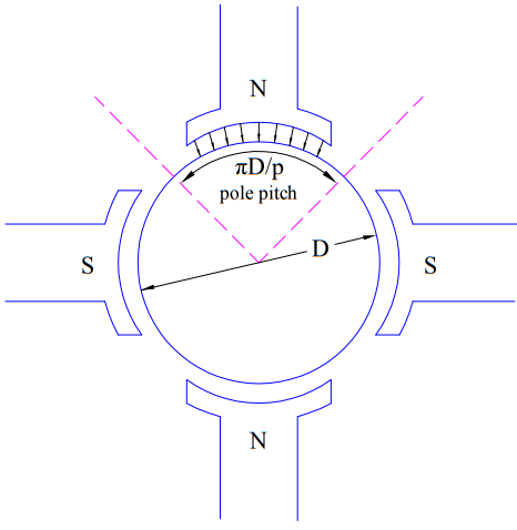
Torque equation of DC Motor gives the amount and nature of electrical torque Te developed whenever it is taken into service. Basically the performance of DC machine centers around two equations. One is EMF equation and another is Torque Equation. Therefore, understanding of torque equation is a must for performance analysis. These equations equally apply for both i.e. generator and motor operation mode of DC machine. In generator mode of operation, this torque opposes the prime mover torque to convert the mechanical energy into electrical energy. But, in motor operation mode, electrical torque is utilized to drive the load coupled to motor shaft.
Torque in DC Motor depends upon the constructional as well as operational parameters. Constructional parameters include number of poles P, number of conductors Z and number of parallel paths ‘a’ in armature. Operational parameters include armature current Ia and field excitation.
Torque produced in a DC Motor is given as
Te = KaØIa …….(1)
Where Ø = Total flux per pole
Ia = Armature current, and
Ka = (PZ/2πa).
Since Ka depends upon the constructional design of DC Motor or generator, it is known as armature constant. Here P is number of poles, Z is total number of armature conductor and ‘a’ is the number of parallel paths in armature.
Equation (1) is the torque equation for DC machine. This equation is applicable for both DC Motor and Generator.
Derivation of Torque Equation of DC Motor
As we know that, a current carrying conductor experiences a force when kept in external magnetic field. This force is given as
F = iLB ……..(2)
where i is the current flowing in the conductor, L is length of conductor and B is the magnetic flux density. We will apply this concept to derive the torque equation of DC machine. But before we go to derive, there are some important points which must be known:
- In DC machine, rotor carries the armature winding and field winding is mounted on stator. Thus rotor conductors are in the magnetic field produced by stator field winding.

- Unidirectional torque is produced in DC machine. This is because, as we go from one pole to another pole, the direction of conductor current reverses. What does this exactly mean? This means when the direction of magnetic field changes (as we move from North to South Pole) the current direction also changes resulting in unidirectional torque.
Let us now move forward to derive the torque equation using (2). Since Ø is the total flux per pole and P is the total number of poles, therefore total air gap flux (Øt) will be
Øt = PØ
If D and L are the rotor diameter and the length of the machine in meters, then
Cross Sectional area of machine = πDL
Therefore,
Magnetic Flux Density B = Total Flux / Area
= (PØ / πDL) Wb/m2
Again, total armature current is Ia and number of parallel path is ‘a’, therefore current in each conductor = (Ia / a)
Now, from equation (2),
Force on each conductor, F = (Ia / a) (PØ / πDL) (L)
= (IaPØ / πaD)
This force F is causes the rotor to rotate around its axis. The perpendicular distance of this force F from the rotor axis is (D/2). Therefore the torque produced by this force for a single conductor is given as below.
Torque on single conductor = FD/2
= (IaPØ / 2πa)
As there are total Z conductors, the total torque is the sum of torques acting on all the Z conductors.
Total Torque Te = Zx(IaPØ / 2πa)
= (ZP / 2πa)Ø Ia
Assuming Ka = (ZP / 2πa) = constant for a given machine
Torque equation of DC Motor, Te = KaØIa
⇒Te α ØIa
Torque of a given DC Motor depends on the armature current and magnetic flux.
This really helps, helping to get clearer understanding about motor’s torque.
Thank you on this note!!!!!!!!!!!!!!!!!!!!!!!!!!!
We are glad to hear this.