We know that torque equation in synchronous motor or generator is directly proportional to the stator filed strength, rotor field strength and the sine of angle between them. This is true for all rotating electrical machine.
If Fs, Fr and λ be the stator field strength, rotor field strength and angle between Fs & Fr, then the torque is given as
Te = FsFrSinλ
The above torque equation is a general equation applicable for all rotating electrical machine. In this post we will derive a general torque equation for synchronous machine. For this purpose, let us consider a uniform air gap two pole machine as shown below.
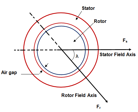
Current in the stator winding produces stator mmf which is assumed to be sinusiodally distributed in the air gap periphery. The peak value of this stator mmf Fs is directed along the stator winding axis as shown in figure. In the above figure, Fs is taken horizontal with Fs directed from left to right. Similarly, rotor current produces rotor mmf which is also assumed sinusiodally distributed in the air gap. The peak value of rotor mmf Fr is along the rotor winding axis as shown in figure. It should be noted that Fs and Fr is the peak value of resultant mmf due to all stator and rotor winding.
These stator and rotor mmf in turn causes appearance of stator and rotor poles. Stator mmf Fs causes appearance of North pole in the left side whereas South pole at the right side of stator. Similarly, North and South pole are produced due to rotor mmf as shown in figure. These stator and rotor magnetic poles interact with each other and tend to align their magnetic axis. This results in development of electromagnetic torque.
In the above figure, the length of air gap is ‘g’ and average radius i.e. average of stator and rotor radii is ‘r’. The effective axial length of synchronous machine is ‘l’.
For deriving general torque equation for synchronous motor / generator, following assumptions are made:
- The stator and rotor iron have infinite permeability. This effectively means that saturation is neglected.
- All the magnetic flux crosses the air gap perpendicularly. This means that flux leakage is assume to be absent.
- The air gap length is very small when compared to the axial length of synchronous machine. This means that the value of flux density at stator surface, rotor surface and at any point in the air gap is same.
- Only fundamental sine component of stator and rotor mmf wave is considered.
Based on the above assumptions, the torque equation for any rotating electrical machine is given as
Te = -(π/8)P2ØFsSinδs Nm
= -(π/8)P2ØFrSinδr Nm
P = Number of poles
Ø = Resultant air gap flux per pole
Fr = Rotor mmf
Fs = Stator mmf
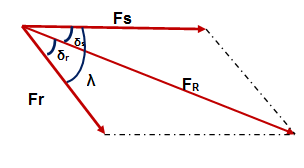
In the above phasor, FR is the resultant of stator mmf Fs and rotor mmf Fr. The angle between Fr & FR i.e. δr is called the load angle. Similarly, the angle between the resultant air gap flux FR and Stator mmf Fs i.e. δs is called load angle. The angle λ between the stator and rotor mmf is called the torque angle.
The negative sign in the torque equation of synchronous machine implies that electromagnetic torque acts in such a direction to minimize the torque angle λ. It must be noted here that, the above torque equation is valid not only for synchronous motor or generator rather it is valid for all rotating electrical machine.
Hi,Im charumathe persuing 3rd year EEE.
My question is On which basis the value π/8 is taken?
This constant value is arrived when you do the full derivation.
where can i find the full derivation of this equation