Torque Slip Characteristics is the graphical relationship between the torque and slip of an Induction Machine. This characteristic is very useful for the stability analysis of the machine.
Electromagnetic torque in an Induction Machine is given as
Te = [Kx(r2/s)] / [(Re + r2/s)2 + X2] …………………(1)
Where K = Constant
From the above equation, the variation of electromagnetic torque can be plotted for different values of slip while assuming that the motor is connected to a constant frequency voltage source. This plot so obtained, also called Torque Slip Characteristics, is shown in figure below.
From the above, torque slip characteristics, it can be said that, there are three regions of operation of induction machine i.e. when s <0 , s>1 and 0<s<1. We will consider each of the regions in the following discussion.
Case1: 0<s<1 i.e. Motoring Mode
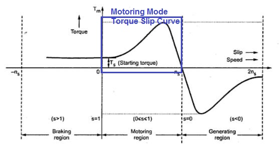
As the slip is less than 1, this means that the speed of rotor is less than synchronous speed and the rotor is rotating in the direction of rotating magnetic field. Also, electromagnetic torque for this region of operation of induction motor is positive as clear from the characteristics and equation (1). This means that, this region of operation, is the normal operation of machine and that too, as Induction Motor.
It must be noted that, when s = 0, electromagnetic torque is zero just because the machine rotor is rotating at the synchronous speed in the direction of rotating magnetic flux, hence the relative speed between them is zero which causes no emf to be developed in the rotor and hence no torque is produced.
Also, note that, at the starting i.e. s = 1, there exists some finite torque, this finite torque corresponds to the no load torque requirement of the machine due to inertia of rotor and windage, friction and bearing losses.
Thus for motoring mode, the torque slip characteristics will be like
Therefore, if someone asks you to draw the torque slip characteristics of Induction Motor then you should only draw the portion marked in the figure above.
Case2: s<0 i.e. Generating Mode
As the name suggest, the machine should be producing electrical power. But electrical energy can only be produced if we supply input mechanical energy, this means in Generating mode, we must be using prime mover to rotate the rotor and stator is connected to constant frequency voltage source. Now if the rotor is rotated at a speed more than the synchronous speed, the slip will be negative and as per equation (1), electromagnetic torque will be negative which means that electromagnetic torque is opposing the prime mover torque. This opposition is necessary for the conversion of mechanical energy to electrical energy.
It shall be noted that, even though rotor is rotated a super synchronous speed but stator is not connected to constant voltage source then there will not be any generation action.
Case3: s>1 i.e. Braking Mode
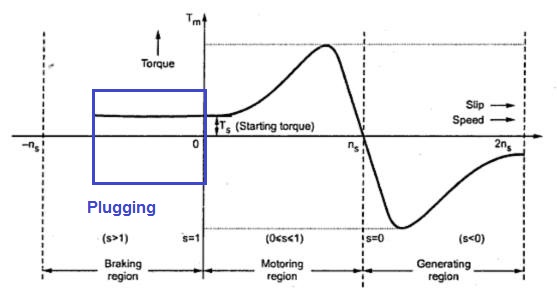
Slip more than 1 means the rotor is revolving opposite to the direction of rotating magnetic field; this means the electromagnetic torque will act in a direction opposite to the direction of rotation of rotor. But how can we achieve s>1?
Well, we can use prime mover and can rotate the rotor in a direction opposite to the rotating magnetic field. But this method is rarely used. Rather the practical application of s>1 is exploited in quick stopping to induction motor by just changing any of the two phase leads.
Suppose the rotor of induction motor is revolving in clockwise direction which means magnetic flux is also rotating in clockwise direction. Meanwhile we change any two phase leads. Changing the phase leads will cause change in direction of rotation of magnetic field i.e. anticlockwise direction. This change in direction of magnetic flux will cause electromagnetic torque to reverse its direction but due to inertia the rotor will continue to rotate in clockwise direction. Thus, electromagnetic torque is anticlockwise and rotor is rotating in clockwise direction. Therefore rotor will rotate in deceleration and will soon come to a stop. But as soon as the motor come to a stop, the stator must be disconnected from supply else the rotor will start rotating in anticlockwise direction. This method of Braking is known as Plugging. The Braking region in torque slip characteristics is marked in the figure below.


How much negative slip can withstand by a Induction Generator? If it will go beyond that what will happen to generator?
It is better to refer Manufacturers’ Instruction for such data.