Taps are connections to the, usually high-voltage winding of a transformer which enables changes to the turns ratio to be made in order to make changes to the secondary voltage to compensate, where necessary, to a fall in terminal voltage below the regulatory allowance.
Off-load tap-changing mechanisms require the transformer to be isolated before its tap settings can be adjusted, and is normally the case with smaller distribution transformers.
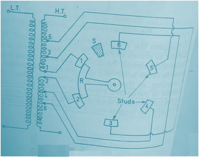
In this post we will focus on Off-Load Tap Changer. Off-Load Tap Changer is used for seasonal variation in voltage. A typical simplified diagram of Off-Load Tap Changer is shown in figure below.
As shown in figure above, the winding is tapped from six locations corresponding to which six studs are provided. The six studs are arranged along the periphery of a circle. The rotatable arm R can be rotated from a hand wheel mounted outside the Transformer Tank.
- If the position of rotatable arm is at stud 1-2, the whole winding is circuit.
- If the position of rotatable arm is at stud 2-3, 97.5% of winding is in circuit.
- If the position of rotatable arm is at stud 3-4, 95% of winding is in circuit.
- If the position of rotatable arm is at stud 4-5, 92.5% of winding is in circuit.
- If the position of rotatable arm is at stud 5-6, 90% of winding is in circuit.
Thus the position of the rotatable arm R determines the voltage of secondary. An extra Stud Stop is provided to ensure that Rotatable arm R is not rotated further in clockwise direction else the studs 1-6 will be shorted which means only lower part of winding is cut out, which in turn will result into undesirable mechanicalstress (how mechanical stress develops).
In case of Off-Load Tap Changer, it must be ensured that Transformer is de-energized as Off-Load Tap Changing is not Make Before Break type. If the Off-Load Tap Changer is used while the Transformer is energized, heavy sparking will take place which will damage the winding and insulation.
