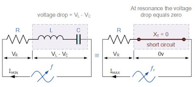
RLC Series Circuit is shown below. We will consider RLC Series Circuit for Resonance.
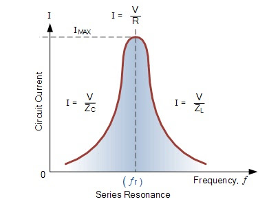
Since the current flowing through a series resonance circuit is the product of voltage divided by impedance, at resonance the impedance, Z is at its minimum value, ( =R ). Therefore, the circuit current at this frequency will be at its maximum value of V/R as shown below.
The frequency response curve of a series resonance circuit shows that the magnitude of the current is a function of frequency and plotting this onto a graph shows us that the response starts at near to zero, reaches maximum value at the resonance frequency when IMAX = IR and then drops again to nearly zero as ƒ becomes infinite. The result of this is that the magnitudes of the voltages across the inductor, L and the capacitor, C can become many times larger than the supply voltage, even at resonance but as they are equal and at opposition they cancel each other out.
As a series resonance circuit only functions on resonant frequency, this type of circuit is known as an Acceptor Circuit because at resonance, the impedance of the circuit is at its minimum so easily accepts the current whose frequency is equal to its resonant frequency.
It should be notice that as the maximum current through the circuit at resonance is limited only by the value of the resistance, the source voltage and circuit current must therefore be in phase with each other at this frequency. Then the phase angle between the voltage and current of a series resonance circuit is also a function of frequency for a fixed supply voltage and which is zero at the resonant frequency point when: V, I and VR are all in phase with each other as shown below. Consequently, if the phase angle is zero then the power factor must therefore be unity.


so, is this the principle behind power factor correction capacitor banks on a distribution line ?