According IEC, Knee Point Voltage of a Current Transformer is defined as the voltage at which 10 % increase in voltage of CT secondary results in 50 % increase in secondary current. If you carefully read the definition, you will notice that it is something related to saturation of Current Transformer CT. Never mind, I will explain what exactly as Knee Point voltage mean and what is its significance.
We know that CT core is made of CRGO (Cold Rolled Grain Oriented Silicon Steel). When the primary of CT is energized a working mmf is produced in the core. To produce a working mmf, excitation current Ie is taken. This mmf produces a flux inside the core of CT which links with the secondary winding and as per the Faraday’s Law of Electromagnetic Induction, an emf is generated across the terminals of CT secondary. The emf induced in the CT secondary terminal is given as
E = 4.44fNØ
Where f is frequency of supply, N is number of secondary turns and Ø is flux in the core of CT.
But Ø is directly proportional to mmf and mmf in turn is directly proportional to current. Thus if we increase the current, flux Ø generated in the core will increase till the core saturates. Thus there must be a point where from the flux do not increase in the same proportion as the increase in current. This point is called Knee Point. After discussing this much, we can at least say that Knee Point is something related with Saturation of CT core. If there is something called saturation, then we must draw saturation curve of the CT core to have more insight.
You may like to read
For drawing CT saturation curve, we apply voltage in the CT secondary (keeping primary open) in step of 10% of rated voltage till 120% and read the secondary current using Clamp Meter. All the readings are noted in table and a curve is drawn between applied voltage V and excitation current Ie. The curve drawn will look like as shown in figure below.
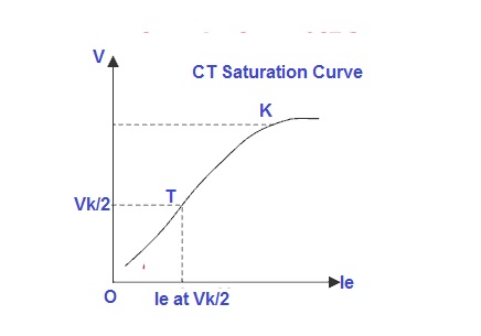
Carefully observe the saturation curve shown above. It is quite clear that beyond point K, we need to increase current to a larger extent to have some increase in voltage. This because the curve beyond point K becomes non-linear. The voltage at point K i.e. Vk is called Knee Point Voltage. This is the reason, in definition it is said that Knee Point Voltage of a Current Transformer is defined as the voltage at which 10 % increase in voltage of CT secondary results in 50 % increase in secondary current. This means that an increase in 50% current will lead to just an increase in 10% voltage. Therefore slope at Knee Point Voltage will be,
Slope = Increase in Voltage / Increase in current
= 0.1/0.5
= 0.2
Knee Point Voltage of Current Transformer is of importance in Protection Class CT i.e. where CT is used for protection purpose. Protection Class CT is normally specified as PS (Protection Special). PS is defined by knee point voltage of current transformer Vk and excitation current Ie at Vk/2. The Burden of CT when used for protection purpose is quite high when compared with Metering Class CT, which means that voltage drop across the burden will be high. But voltage drop across the burden is equal to the voltage across the CT secondary and if the voltage across the CT secondary is high then it may drive the CT to saturate in normal condition. Therefore Knee Point voltage of Protection Class CT must be more than the voltage drop across the burden to maintain CT core in its linear zone.
Very Informative! This blog is great source of information which is very useful for me. Thank you very much for sharing this!
Transformer Manufacturer in India
nice bro…
Thank you Mani!
Thank you sir. Good knowledge and very good information in a simple way.
Please share if you like it. Thank you!
thanks।।।।।।।
Show Calculation for 220 KV Protection Class C.T with ratio 500/1.
What calculation you wanted me to show?
How the KNEE POINT VOLTAGE of PS class CT is calculated. No graphical presentation, only formula with example.
Thank you sir. Good knowledge and very good information in a simple way.
Thank you Ashok! Request you to share the post.
Excellent Explanation. I have read about knee point voltage from textbooks and websites, no one explains it better than you. Thank you for the good work.
I hardly comment on people’s site but you deserve more
Thank you very much for your kind words.