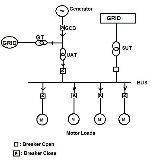
Following points should be noted form the above figure:
1) Two sources are connected to the motor BUS, one is through UAT CB and second one is through SUT CB. UAT means Unit Auxiliary Transformer while SUT means Start-up Transformer. Primary of UAT is connected to Generator output and secondary to the motor bus. UAT CB remains normally close and thus feeds the motor loads connected to the bus.
2) Primary of Start-up Transformer (SUT) is connected to Grid while its secondary to the motor bus. SUT is basically meant to import auxiliary power from the Grid in case of fault in the UAT or Generator tripping and GCB (Generator Circuit Breaker) open.
3) Power evacuation to Grid is through the Generator, GCB and Generator Transformer (GT). Auxiliary loads can also be supplied through the GT-UAT combination in case of Generator tripping and GCB open.
Keeping all the above points in mind, when there is a fault in UAT, the power supply to motor bus will be lost and subsequently motor loads will trip on under-voltage protection (normally set at 20% of nominal voltage). This will result into plant outage and loss of production. To avoid such outage, Auto Transfer System (ATS) is used. ATS senses the fault in old source and restores the power supply through alternate source so that the motor loads are not tripped. For our example, when ATS relay senses fault in UAT, it gives tripping command to UAT CB and closing command to SUT CB. Thus power supply to motor bus is restored. The operation of ATS relay must be fast enough to ensure that motor loads are not tripped on under-voltage. So the question arises how fast ATS should be? How do we decide the time window within which the auto transfer cycle should be completed?
The time window for auto transfer to operate is dependent on motor bus spin down characteristics. Let us first understand the bus spin down characteristics to answer the questions.
Motor Bus Spin down Characteristics:
The bus voltage will instantaneously become zero if all the loads connected to the bus are resistive in nature. Isn’t it? Yes, but since the loads connected to the bus are motor loads i.e. inductive loads therefore on loss of supply to the bus, the voltage of the bus will not instantaneously decay to zero. It will take some definite time to decay down. The voltage decay time of the motor bus will depend on the time constant (L/R ratio). This time constant can easily be calculated by the equivalent open circuit parameter of connected loads. The more the inductance of the system, the more will be the time constant and hence the more will be time for voltage to decay down to zero.
Let us consider the same thing in different but practical way. Suppose the motor loads are operating normally and suddenly power supply to the bus is lost. What will happen? The motor will slowly decelerate. The rate of deceleration will be inversely proportional to the inertia of the connected load to the motor. The more is the inertia of load to the motor; the lower will be rate of deceleration. This means that a heavy motor will take more time to stall. During the period of deceleration, the motors will behave like an induction generator due to trapped magnetic flux in its air gap. This will result into back feeding of voltage at to bus till the trapped residual magnetic flux is dissipated. The frequency and phase of residual bus voltage will also decay with the deceleration of motor and eventually will become zero. Thus there are three important parameters from auto transfer point of view. These are
1) Magnitude of the residual voltage
2) Decay time of this residual voltage
3) The phase angle of the residual voltage with respect to healthy bus
From the above discussion of Spin down Characteristics, it is quite clear that the motor bus voltage should not decay to such an extent that under-voltage relay is operated and motor is tripped. Again for ATS to restore power supply through alternate source, the alternate source and residual motor bus voltage should be in synchronism. This means that the condition for synchronism should be satisfied. Thus the whole cycle of auto transfer must be completed within a specified time decided by the decay time and mode of auto transfer. Thus an ATS relay must take bus voltage, old source voltage, new source voltage and breaker status as an input as shown in figure below.

Bus auto transfer can either be sequential or parallel. In parallel mode, new source breaker is first closed and then old faulty source breaker is opened. Whereas in sequential mode, first old faulty source breaker is opened and then new healthy source breaker is closed. But the parallel mode has some disadvantage. The main disadvantage is availability of dual source fault current and the high reactive currents which may result due to angular difference between the two sources. Sequential transfer mode eliminates this problem. Fast, in-phase and slow transfer are the available sequential transfer modes.
Modes of Auto Transfer:
Based on the system condition like voltage, frequency and phase angle of motor bus, auto transfer can take place in three different modes: Fast Transfer, In-Phase Transfer and Slow Transfer.
Fast Transfer:
Fast transfer is a supervised open circuit transfer scheme. Supervised open circuit transfer means that the alternate source breaker is closed with synchronism check with motor bus and open circuit means alternate source breaker is closed when the faulty source breaker is confirmed to be open by the ATS relay. This scheme minimizes the interruption of power to the bus, while avoiding a potentially unsafe parallel operation of both the sources. In the fast transfer mode, the decision to supply transfer is done on the basis of comparing the phase angle and voltage magnitude of the bus with that of the new source. The time window for fast transfer will be governed by spin down characteristics of motor bus of the utility. Thus for one utility it may be 200 ms while for some other utility it may be 250 ms. Similarly time frame for in-phase transfer will vary from industry to industry.
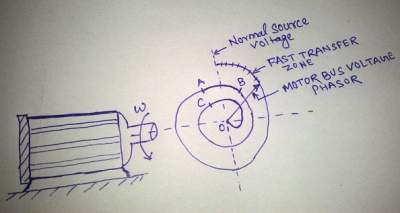
In-Phase Transfer:
In-Phase Transfer takes place when the first opportunity to supply transfer is missed. Careful observation of spin down characteristic of motor bus reveals the zone for fast transfer. Once the time window for fast transfer is elapsed, ATS Relay need to wait till the phase angle of residual bus voltage again comes within synchronism limit (normally this limit is 20 degree). Zone AB in the spin down characteristics shows the region where in-phase transfer can take place. Thus the time window for in-phase transfer is generally more. This mode is also an open circuit transfer scheme. The main advantage of the in-phase transfer mode is the ability to safely transfer the bus to the new source, even if the fast transfer is blocked, without necessarily having to trip the motors.
Slow Transfer:
The slow transfer or residual voltage transfer method is the slowest transfer of the bus to the new source. Basically slow transfer is a dead bus transfer scheme where the new source is connected to bus when the bus is dead. During this time all the motor loads are tripped on U/V protection. Tripping of motor loads is necessary to avoid simultaneous re-acceleration on supply restoration.
Various microprocessor based high speed programmable ATS Relays are available. The above three modes may be enabled in the relay with appropriate setting like time window for fast and in-phase transfer, residual voltage magnitude, phase difference between the healthy source and residual bus voltage etc. This relay decided for the suitable transfer mode and direction of transfer based on its setting and breaker configuration. Breaker configuration means, if UAT CB is open and SUT CB is close, ATS will detect transfer direction from SUT to UAT and UAT CB will be closed on fault in SUT. Breaker auxiliary contacts are wired up to the relay.
Thanks You explained very well