What is RVDT?
Definition: Rotary Variable Differential Transformer or RVDT is an inductive transducer which converts angular displace to an electrical signal. Unlike LVDT, the input of this transducer is differential value of rotary variable i.e. angular rotation (dƟ) to generate voltage output.
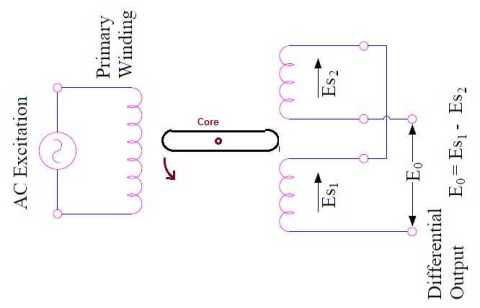
Construction:
Like every transformer, RVDT has two types of winding i.e. Primary winding and Secondary winding. The primary and secondary winding are wound on a former. There are two secondary winding having equal number of turns. These winding are placed on either side of the primary winding identically. A cam shaped magnetic core made of soft iron is connected to a shaft. This magnetic core can be thus be rotated in between the winding. Carefully observe the figure below to understand the construction and working principle.
The construction of LVDT and RVDT is almost same. The only difference in their construction is that in RVDT, the core is cam shaped and may be rotated between the windings by means of a shaft. You should read LVDT – Construction and Working Principle to understand the constructional detail.
Working Principle:
The reluctance seen by the primary mmf changes with the rotation of cam shaft. This results in change in the magnetic flux with rotation of the cam shaft. Due to this change in magnetic flux with rotation of cam, the flux linkage of secondary winding also changes. Therefore, as per the transformer action, an emf is induced in secondary winding. The magnitude of induced emf will depend on the rate of change of rotation. The more the rate of change of rotation, the more will be the rate of change of flux w.r.t. and hence more emf will be induced.
As can be seen from the figure, the two secondary winding are connected in series but in phase opposition. This is done to get a single output voltage from the transducer. If Es1, Es2 and E0 be the emf induced in the two secondary winding S1 & S2 and output voltage respectively then
E0 = Es1 – Es2
Under normal condition of RVDT, the flux linkage of both the secondary winding are same due to their symmetrical placing with respect to primary and core. Therefore, the induced emf Es1 and Es2 are equal and hence output voltage E0 of the transducer in such condition is zero. Therefore, normal position of RVDT is called NULL position.
Clockwise rotation of cam causes an increasing voltage Es2 in one of the one secondary winding while counter clockwise rotation leads to increase in voltage Es1 of another secondary winding. Thus the direction as well as magnitude of angular rotation can be ascertained from the magnitude and phase of transducer output voltage. Phase of transducer output voltage means whether (Es1 – Es2) is positive or negative. In case of anti-clockwise rotation, the value of Es1 will be more than that of Es2 and hence (Es1 – Es2) will be positive. In this case we say that output voltage E0 is in phase with the primary voltage. With the same logic, when cam is rotated in clockwise direction, the output voltage will be negative i.e. out of phase with primary voltage.
Thank you. I find your post quite insightful. So thank you
Thank you!!
Sharing knowledge is great and respectable work even it is a small bit of content , thank you