Transformer is an electromagnetic device that transfers electric power from one circuit to another at a constant frequency. It step-up or step-down the voltage level from one circuit to another at almost constant power. As, voltage transformation take place at a constant power, there is a change in circuit current. For example, when transformer increase the voltage, the current decreases as Power = Voltage x Current. In this post, we will discuss about the theoretical and practical aspect of construction of transformer.
Construction of Transformer:
A transformer essentially consists of three components: Core, HV Winding and LV Winding. Rest everything like Conservator, Buchholz Relay, Radiator, Breather etc. are auxiliaries of transformer. These auxiliaries are required for satisfactory operation of transformer. Let us focus now on the construction of Transformer.
Transformer Core: The core of transformer is a stack of thin silicon-steel lamination of thickness 0.35 mm. These lamination are insulated from each other by thin layer of varnish paint. This is done to reduce the eddy current losses. To reduce the core losses, a high permeable magnetic material, called Cold Rolled Grain Oriented Sheet Steel (CRGO), is used as the core material. Figure below shows a lamination of CRGO.

These lamination are stacked one over another two make the transformer core. In the above figure, you will see sticks pasted on the lamination. Theses sticks are called runner sticks. It is provided to facilitate transformer core cooling by providing a path for the flow of oil in case of oil cooled transformer. But runner strip is only provided in some selected lamination. It should not be confused that it is in all lamination. Figure below shows how a transformer core is assembled using these CRGO lamination.

Just have a closer look at the core assembly. Are you finding that stacking of laminations edges are done at 45 degree? Just see the outer face to realize this. This type of core is known as 45 degree mitered core. You know why lamination edges are made to have stacked at 45 degree angle?
Let us consider the figure below.

If the stacking were done at 90 degree angle, the magnetic flux would have not been flown to the core due to full rebounded after striking at 90 degree as per the law of reflection. But when stacking is done at 45 degree, the angle of incidence of magnetic flux wave is obviously 45 degree; therefore this flux will get reflected with an angle of reflection of 45 degree. Thus the flux will go from limb to yoke without any re-bounce.
Transformer Winding: HV and LV windings of transformer are made up of copper conductor. This copper conductor is enameled and insulated using Kraft paper.
Well, after having a bit idea of transformer core and winding construction, let us now proceed to assemble both of them.
On the basis of the core construction and winding arrangement, there are basically two types of Transformer. These are Core Type Transformer and Shell Type Transformer.
Construction of Core Type Transformer:
A core type transformer is shown below.
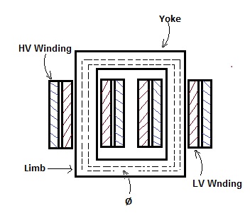
The vertical part of the magnetic circuit is called the Limb over which winding is wound. The horizontal portion is called the Yoke. As can be seen in the above figure, the transformer winding is surrounding the magnetic core.
In core type transformer, winding is wound on both the limbs. First low voltage winding is wound on the core followed by high voltage winding. This is done to minimize magnetic flux leakage. It must be noted here that, LV winding is placed on the core to have minimum insulation requirement. Due to its design, total flux Ø flows through the core as obvious from the above figure. An internal view of a real core type power transformer is shown below.

The above figure will definitely give you an idea of how the assembled core and transformer windings are integrated. Limb, Yoke and windings are shown in the figure. I would suggest you to hold here for two minutes and realize the construction of transformer.
Construction of Shell Type Transformer:
Figure below shows the construction of shell type transformer.
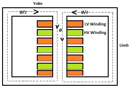
In shell type transformer, core surrounds the windings as clear from the above figure. The HV and LV windings are only wound on the central limb. These HV and LV windings are interleaved. It this design, the bottom and top LV coils are made half in size as compared to other. Shell type transformer is generally used for low voltage and low power applications. Half of the total flux Ø flows in the Yoke and two outer limbs whereas total flux Ø flows through the central limb.
In Shell type transformer, iron requirement for the construction of core is more but the copper requirement for winding is less when compared to core type transformer.
Hope you enjoyed the post. Please write in comment box for any value addition or suggestion. Thank you!
thnx
Really good article you have covered in much depth information about the construction of transformers. Especially differentiating between the core and the shell type of transformers. But Still I would like to know how you have the shell type would be useful for current transfomers