Electrodynamometer wattmeter and Low Power Factor (LPF) wattmeters are mostly similar in construction and operation, except for the following modifications are carried out in the electrodynamometer wattmeter to convert it into a LPF wattmeter:
- Pressure coil resistance is kept low to increase the torque.
- Compensating coil is used to compensate the Pressure coil current.
- Capacitor is connected across the pressure coil to reduce the error due to pressure coil inductance.
- Control torque is made very less for high deflection.
Why a LPF Wattmeter is needed?
As the name suggests the low power factor meter are the instruments that measures lower values of power factor accurately. There is a requirement of low power factor meter because, the usage of ordinary electrodynamometer wattmeter to measure power factor of a low pf load gives inaccurate results.
Now there are two main reasons that would suggests us that we should not use ordinary wattmeter in measuring the low value of power factor.
- The value of deflecting torque is very low even though we fully excite the current and pressure coils.
- Errors due pressure coil inductance.
Modifications:
Pressure coil current:
The pressure coil circuit is designed to have a low value of resistance, so that the current flowing through it is increased to give an increased torque.
Compensation for Pressure coil current:
In this category two cases arise and their diagrams are shown below:
In the first category both the ends of the pressure coil is connected to supply side i.e. current coil is in series with the load. The supply voltage is equal to the voltage across the pressure coil. Thus in this case we have power shown by the first wattmeter is equal to the power loss in the load plus power loss in the current coil.
In the second category, the current coil is not in series with the load and the voltage across the pressure coil is not equal to the applied voltage. The voltage across pressure coil is equal to the voltage across the load. In this power shown by the second watt meter is equal to the power loss in the load plus the power loss in the pressure coil.
Therefore, it is absolutely necessary to compensate for the pressure coil current in a LPF wattmeter.
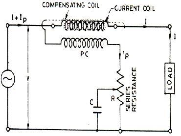
The compensating coil is connected in series with the pressure coil circuit and is made nearly identical to the current coil. The current coil and the compensatig coil carry currents of (I + Ip) and Ip, respectively, and they produce fields corresponding to these currents. The compensating coil is so connected that it opposes the field of the current coil. Thus, the resultant field is due to current I only.
Hence, the error due to pressure coil current flowing in current coil is neutralized.
Compensation for Inductance of PressureCoil:
The error caused by pressure coil inductance is
Error=VIsin(Ф)tan(β)
With low power factor, the value of Ф is large, and therefore the error is correspondingly large. The compensation of the error caused by the inductance in the pressure coil is done by connecting a capacitor across a part of series resistance in the pressure coil circuit.
Small Control Torque:
LPF wattmeters are designed to have a small control torque so that they give full scale deflections.
Incorporating all these modifications into an electrodynamometer wattmeter gives the following circuit:
A modern low power factor meter is designed such that it gives high accuracy while measuring power factors even lower than 0.1.
Checkout Electrical and Electronics Measurement and Instrumentation by A.K Sawhney…