Parallel operation of two or more Transformers means that all the Transformers Primary is connected with the common supply and their Secondary are feeding to a common bus through which load is connected. Parallel operation of Transformers requires that their Primaries as well as Secondaries are connected in parallel.
Parallel operation of two or more Transformers has many advantages when compared with a single large Transformer. Though using single large Transformer instead of two or more Transformers connected in parallel are cheap but still due to the following advantages, parallel operation of Transformers are preferred where required:
- With two or Transformers, the Power System becomes more reliable. Let one Transformer develops a fault, then the faulty Transformer can be removed from the circuit while maintaining the power supply at a reduced level through healthy Transformers. Thus in this way, Power System becomes more reliable.
- Depending upon the load, Transformers can be switched ON / OFF. In this way, Transformer losses are reduced and the system becomes more efficient and economical.
- If the power demand increases with time then extra spare Transformer can be taken into service to meet the power demand.
Condition for Parallel Operation of Transformers:
The various conditions which must be satisfied for the parallel operation of two or more Single Phase Transformers are:
a) The Transformers must have the same voltage ratio i.e. with Primaries of Transformers connected to the same supply; their Secondaries must have the same voltage.
b) The equivalent leakage impedance in Ohm should be inversely proportional to their respective kVA rating. In other words, we can say that all the Transformers should have their per unit leakage impedance based on their own kVA rating equal.
c) The ratio of equivalent leakage reactance to equivalent resistance i.e. xe / re should be same for all the Transformers.
d) The Transformers must be connected properly in view of their polarities.
It shall be noted that condition a) must be satisfied strictly for parallel operation of Transformers. A difference in Secondary voltage will lead to circulating current in the Secondary winding which may damage the winding.
If the two Transformers A and B are of equal voltage ratio, that means equal secondary no load voltage. If the primary leakage impedance drop for the Transformers A and B are same then their Secondary terminal voltages Ea and Eb must be same and hence there will not be any circulating current.
Ea = Eb
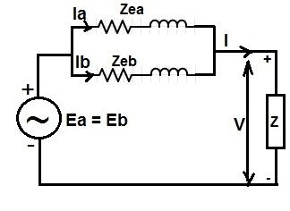
The equivalent circuit for two Transformers A and B referred to secondary side are shown below.
Let us consider the left side figure shown above. Here V is the common Secondary terminal voltage, load current I is shared as Ia and Ib by the Transformers A and B respectively. The Load impedance is Z.
The voltage equation for Transformer A,
Ea – IaZea = V = IZ
Since, Ea = Eb so
Eb – IaZea = IZ …………………(1)
Voltage equation for Transformer B,
Eb – IbZeb = V = IZ ………………(2)
From equation (1) and (2),
Eb – IaZea = Eb – IbZeb
Therefore,
IaZea = IbZeb
We see that equivalent leakage impedance drop for both the Transformers are equal, therefore we can redraw the circuit model as shown below.
As the total load current I is shared by the Transformers A and B, therefore using Kirchhoff’s Current Law,
Ia = [ Zeb / (Zea+Zeb) ]xI
Ib = [ Zea / (Zea+Zeb) ]xI
Multiplying both sides by load voltage V,
VIa = IVx[ Zeb / (Zea+Zeb) ] ⇒ Sa = S[ Zeb / (Zea+Zeb) ]
VIb = IVx[ Zea / (Zea+Zeb) ] ⇒ Sb = S[ Zea / (Zea+Zeb) ]
When more than two Transformers are operated in parallel, the the voltage equation of these Transformers say Transformer A,B,C,D…., can be written as
Ea – IaZea = Eb – IbZeb=……= IZ = V
If no load voltage of thses Transformers are equal i.e. Ea = Eb = Ec = ….= E then
E – IaZea = E – IbZeb = ….= V
The above equation shows that, Transformer with lower value of full load current must have higher value of equivalent leakage impedance in Ohm to satisfy the above equation. Thus we can say that, for Transformers to share load in proportion to their kVA rating must have equivalent leakage impedance inversely proportional to their kVA rating.
For example, if 1000 kVA Transformer has equivalent leakage impedance Zea = 2 ohm then 500 kVA Transformer must have Zeb = 4 ohm for parallel operation.

