For discussing the effect of Load Encroachment on Distance Protection, we make a steady state model of Transmission Line as shown in figure below.
|
Impedance seen by Relay i.e. Apparent Impedance,
Z = Vi2 (Pij + jQij)/( Pij2 + Qij2)
|
From the above formula, we can make the following conclusions:
- The apparent impedance seen by the Relay is proportional to square of the magnitude of bus voltage. If the bus voltage drops say to 0.9 pu from 1 pu, then Z reduces to 81% of its value at 1 pu. Again, if the bus voltage drops to say 0.8 pu, then the apparent impedance seen by the Relay will drop to 64% of its value at 1 pu.
- The apparent impedance seen by the Relay is inversely proportional to the apparent power flowing on the line. If the apparent power doubles up, the impedance seen by relay will reduce by 50%.
During peak load conditions, it is quite likely that combined effect of both the above mentioned points may reduce the apparent impedance seen by the Relay to sufficiently small value so as to fall in Zone-2 or Zone-3 characteristic. This is quite likely in case of a Relay backing up a very long line. In such a case, Zone-3 impedance setting can be quite large. If the impedance seen by Relay due to large loads falls within the Zone, then it will pick up and trip the circuit after its set time delay. In such case, the relay is said to trip on Load Encroachment. Tripping on Load Encroachment compromises security and it can even initiate cascade tripping which in turn can lead to blackouts.
Therefore it is very important to provide some feature in Relay so that it can distinguish between actual fault and Load Encroachment. How is this done?
As we know that distinguishing feature of load from faults is that loads have large power factor and this leads to Impedance Z with large ratio of R/X. While faults are more or less reactive in nature and the ratio X/R is quite high.
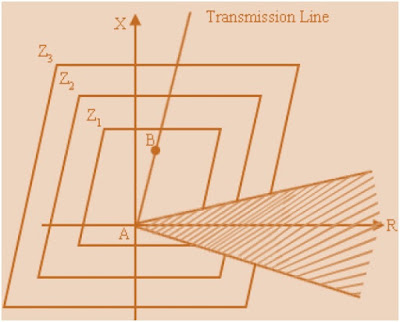
Thus, to prevent tripping on Load Encroachment, the Relay characteristic are modified by excluding an area in R-X plane, which corresponds to high power factor. A typical modified characteristic to account for load encroachment is shown in figure below.
Observe that shaded portion is excluded from the Relay Characteristics to avoid tripping on Load Encroachment. Also, from figure it is clear that for shaded portion, the value of reactance X is low while the value of Resistance is high thereby resulting in high R/X ratio.
The conditions of low value of Z can also arise due to voltage instability or transients associated with electromechanical oscillations of rotors of synchronous machines after a major disturbance like the faults. This can also introduce nuisance tripping. Such tripping is known as tripping on Power Swings.
Thank you! Please write your comment and share this post.


Sir you give exact reasons n u work well on topic . So ty sir to provide this kinds of knowledge . Sir onc think pls provide as many as possible so that we can understand well again ty sir
Thank you Ajju Patel!
Your article is very easy to understand, thank you
Thank you Pokerun!
Nicely explained
Thank you!
on the picture it states that Pij + jQij (with a plus), but on the equation it states Pij – jQij= VixI (with a minus) is this a mistake or is there something that I’m missing sir?
It is a great work with simple and fluent language. Really appreciate your work but I’d like to see your references for further investigation.
Sir,
Can load encroachment enter zone-1, if at all enters how can measured impedance of a relay can be more than particular line section( zone-1) impedance. Violation of KVL. I mean measured impedance will be line impedance + load impedance.