Electric traction means using the electric power for traction system i.e. for railways, trams, trolleys etc. Now a day, magnetic traction is also used for bullet trains.
How does Electric Traction Work?
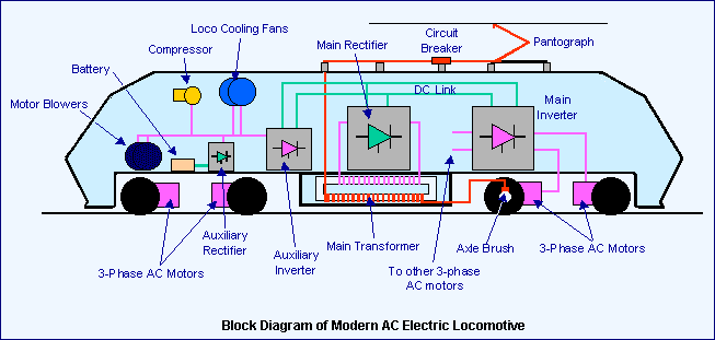
Block Diagram:
In OHE, or overhead electrification systems, the supply of electricity is through an overhead system of suspended cables known as the Catenary. A contact wire or contact cable actually carries the electricity; it is suspended from or attached to other cables above it which ensure that the contact cable is at a uniform height and in the right position. In the following the term Catenary is loosely used even when talking about the contact wire.

The loco uses a pantograph, a metal structure which can be raised or lowered, to make contact with the overhead contact cable and draw electricity from it to power its motors. Usually it goes first through a transformer and not directly to the motors.

The pantograph structure may be in the form of a single arm — a single open bent angle (‘>’) — or in a diamond (rhombus) form (‘<>’). The diamond form was more common for the DC locos. Newer locos almost always have the single arm pantographs. The single arm types are generally oriented with the bend of the pantograph pointing forwards (in the direction of motion) although this is not a strict rule and locos exist with pantographs in both orientations. Compressed air is used to raise the pantograph from its resting position to the raised position where its shoes touch the contact wire.
The return path for the electricity i.e. the return current is through the body of the loco and the wheels to the tracks, which are electrically grounded. Ground connections are provided from the rails at periodic intervals. Since the body of the locomotive and the wheels are all metal they are quite conductive.

Axle brushes are used to electrically connect the rotating axles to the body of the locomotive. Between the wheels and the rails, usually the return current flows well, but conductivity may be reduced in cases of dirt and debris on the rails, or if embedded particles of soot, coal dust, or films of oil, etc. form an insulating layer on the top of the rails. The voltages and currents involved are such that such thin insulating films are easily punctured and a conductive path established at the rail-wheel contact point.
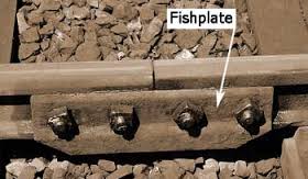
After flowing from the wheels to the rails, the return current flows through the rails and also partly through the earth beneath and along it. Bonding cables or bonding strips are provided at rail joints connecting the rails on either side of a fishplated joint to ensure continuity of return current flow in the rails in case the joint is not conductive because of dirt, rust, and so on, and also to allow permanent way operations that involve loosening the fishplates.
Earthing cables and earth bond conductors are provided periodically to keep the rails firmly connected to earth and at earth potential and therefore prevent them from developing a floating potential or step voltage that may be hazardous.
Modern electric locos have some fairly sophisticated electronic circuitry to control the motors depending on the speed, load, etc., often after first converting the incoming 25 kV AC supply to an internal AC supply with more precisely controlled frequency and phase characteristics, to drive AC motors. Some AC locos (WAG-4, WAM-4) have DC motors, instead. Some AC locos (WAP-5 and WAG-9, both designs from ABB) generate 3-phase AC internally using a thyristor converter system; this 3-phase supply is then used to power asynchronous AC motors. 3-phase AC motors are somewhat more efficient, and can generate higher starting torque.
DC System:
In DC systems with overhead catenary, the basic principle is the same, with the catenary being supplied electricity at 1.5 kV DC. Usually (especially for EMUs) the current from the catenary goes directly to the motors. A DC loco may however convert the DC supply to AC internally using inverters or a motor-generator combination which then drives AC motors.
The generally lower supply voltages of DC systems implies that the currents drawn from the OHE are correspondingly higher. This results in some difficulties, among them the need to use thicker and heavier contact wires and pantographs and to keep the pantograph pressed more firmly against the contact wire causing more wear and tear.
Single system (AC):
The overhead catenary is fed electricity at 25kV AC (single-phase) from feeding posts which are positioned at frequent intervals alongside the track. The feeding posts themselves are supplied single-phase power from substations placed 35-60km apart along the route. The substations are spaced closer (down to 10-20 km) in areas where there is high load / high traffic. These substations in turn are fed electricity at 132 kV AC or so from the regional grids operated by state electricity authorities. A Remote Control Centre, usually close to the divisional traffic control office, has facilities for controlling the power supply to different sections of the catenaries fed by several substations in the area.
Electric Traction is a huge topic which I described in brief. Thank you!