What is LVDT?
Linear Variable Differential Transformer, LVDT is the most used inductive transducer for converting translating linear motion into electrical signal. This transducer converts a mechanical displacement proportionally into electrical signal.
Construction:
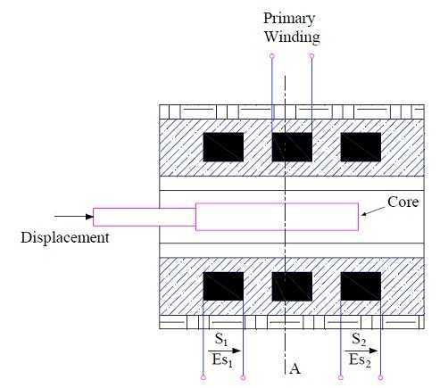
LVDT is a transformer consisting of one primary winding P and two secondary winding S1 & S2 mounted on a cylindrical former. The two secondary winding have equal number of turns and placed identically on either side of the primary winding as shown in figure below.

A movable soft iron core is placed inside the former. Actually the movable core is made of nickel iron with hydrogen annealed. Hydrogen annealing is done to eliminate harmonics, residual voltage of core and thus provides high sensitivity. The movable core also is laminated in order to reduce eddy current loss. The assembly of laminated core is placed in a cylindrical steel housing and end lids are provided for electromagnetic and electrostatic shielding. The displacement to be measured is attached to this movable soft iron core.
LVDT- Working Principle:
Since the primary winding of Linear Variable Differential Transformer (LVDT) is supplied with AC supply, it produces an alternating magnetic flux in the core which in turn link with the secondary winding S1 and S2 to produce emf due to transformer action. The electrical equivalent circuit of LVDT is shown below.

Let us assume that the emf produced in secondary winding S1 is Es1 and that in S2 is Es2. The magnitude of Es1 and Es2 will depend upon the magnitude of rate of change of flux (dØ / dt) as per the Faraday’s Law. The lower the value of ‘dt’, the more will be the emf induced. But lower value of ‘dt’ means that core is moving faster. Thus we can say that the faster the movement of core, the greater will be the magnitude of emf induced in secondary windings.
To get a single output voltage from the Linear Variable Differential Transformer (LVDT), both the secondary winding are connected in series but in phase opposition as shown in figure below.
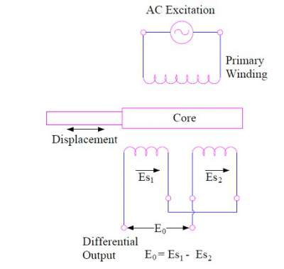
Due to this connection, the net output voltage E0 of the LVDT is given as below.
E0 = Es1 – Es2
Since the secondary windings of LVDT are identical and placed symmetrically on either side of core, therefore under normal position the flux linkage of both the secondary winding S1 & S2 will be same. This means Es1 = Es2 and hence net output voltage E0 of LVDT = 0. This position of soft iron core is called NULL position. Thus NULL position of Linear Variable Differential Transformer is the normal position of movable core where the net output voltage is zero.
Now, as the core can either be moved toward right or left to the null position. Let us now consider such movement of core under two cases.
Case-1: Core is moved left to the NULL position

When core of LVDT is moved to the left of the NULL position ‘O’ as shown in figure above, the flux linkage of secondary winding S1 will become more than that of winding S2. This means the emf induced in winding S1 will be more than S2. Hence Es1 > Es2 and net output voltage E0 = (Es1 – Es2) = Positive. This means that the output voltage E0 will be in phase with the primary voltage.
Case-2: Core is moved right to the NULL position
When the core of LVDT is moved toward right of NULL position ‘A’, you can guess what will happen? Obviously the emf induced in secondary winding S2 will be more than that of S1. This means Es2 > Es1 and hence net output voltage E0 = (Es1 – Es2) = negative. This means that the output voltage of LVDT will be in phase opposition (180 degree out of phase) with the primary voltage.
From the above two cases, we can have the following conclusions:
1) The direction of movement of a physical quantity can be identified by the output voltage of LVDT. If the output voltage E0 is positive, this means the physical quantity is moving toward left.
2) If the output voltage E0 is negative, this will mean that the physical quantity is moving in the right direction from the NULL position.
3) The amount / magnitude of displacement is proportional to the magnitude of output voltage. The more the output voltage, the more will be displacement. But here is a clue. You can’t take core out of the former; otherwise the output voltage will become zero.
4) In fact corresponding to both the cases i.e. whether core is moving left or right to the NULL position, the output voltage will increase lineally up to a displacement of around 5 mm from the NULL position. After 5mm, output voltage E0 becomes non-linear. The graph of variation of E0 with displacement is shown below.

Carefully observe the above graph. It may be noted from the graph that even at NULL position (i.e. when there is no displacement) there is some output voltage of LVDT. This small output is due to the residual magnetism in the iron core.
Application:
LVDT is used in those applications where displacement ranging from fraction of a mm to few cm. As a primary transducer, it converts the mechanical displacement into electrical signal.
Acting as a secondary transducer, it is sued for measurement of force, pressure, weight etc.
it is nice explanation continuous
Thank you!
Really sooo NYC topic of lvdt
how great you explain lvdt with graph diagram its helpful for new learners like me . can you explain how it will works on dc suply in future
Thank you. Please share if you like the post.