Protection schemes can be divided into two major groups: a) Unit schemes, and b) Non-unit schemes.
a) Unit Scheme:
Unit type schemes protect a specific area of the system i.e. a transformer, transmission line, generator or bus bar.The unit protection schemes are based on Kirchhoff’s Current Law – the sum of the currents entering an area of the system must be zero. Any deviation from this must indicate an abnormal current path. In these schemes, the effects of any disturbance or operating condition outside the area of interest are totally ignored and the protection must be designed to be stable above the maximum possible fault current that could flow through the protected area.
b) Non-unit scheme:
The non-unit schemes, while also intended to protect specific areas, have no fixed boundaries. As well as protecting their own designated areas, the protective zones can overlap into other areas. While this can be very beneficial for backup purposes, there can be a tendency for too great an area to be isolated if a fault is detected by different non unit schemes.
The most simple of these schemes measures current and incorporates an inverse time characteristic into the protection operation to allow protection nearer to the fault to operate first.
The non unit type protection system includes following schemes:
- Time graded over-current protection
- Current graded over-current protection
- Distance or Impedance Protection
Over Current Protection:
It finds its application from the fact that in the event of fault the current will increase to a value several times greater than maximum load current. A relay that operates or picks up when its current exceeds a predetermined value (setting value) is called Over-current Relay. Over-current protection protects electrical power systems against excessive currents which are caused by short circuits, ground faults, etc. Over-current relays can be used to protect practically any power system elements, i.e. transmission lines, transformers, generators, or motors. For feeder protection, there would be more than one over-current relay to protect different sections of the feeder. These over-current relays need to coordinate with each other such that the relay nearest fault operates first.
Use time, current and a combination of both time and current are three ways to discriminate adjacent over-current relays. Over-current Relay gives protection against:
- Phase faults
- Earth faults
- Winding faults
Short-circuit currents are generally several times (5 to 20) full load current. Hence fast fault clearance is always desirable on short circuits.
Primary requirement of Over-current protection is that the protection should not operate for starting currents, permissible over-current, and current surges. To achieve this, the time delay is provided.
Over-current Relay Ratings:
In order for an over-current protective device to operate properly, over-current protective device ratings must be properly selected. These ratings include voltage, ampere and interrupting rating.
Current limiting can be considered as another over-current protective device rating, although not all over-current protective devices are required to have this characteristic
Voltage Rating:
The voltage rating of the over-current protective device must be at least equal to or greater than the circuit voltage. The over-current protective device rating can be higher than the system voltage but never lower.
Ampere Rating:
The ampere rating of a over-current protecting device normally should not exceed the current carrying capacity of the conductors As a general rule, the ampere rating of a over-current protecting device is selected at 125% of the continuous load current.
Depending on the time of operation of relays, they are categorized as follows:
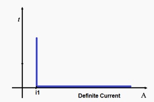
a) Instantaneous Over-current Relay:
Instantaneous Over-current Relay is one in which no intentional time delay is provided for the operation. The time of operation of such Relay is approximately 100 ms. Instantaneous Over-current relay is employed where the impedance between the source and the Relay is small as compared with the impedance of the section to be provided.
Following are the important features of an Instantaneous Over-current Relay:
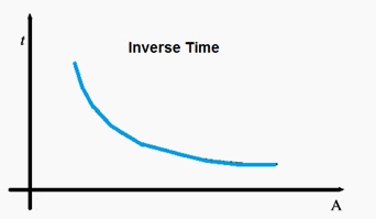
b) Inverse time over current Relay:
Inverse time over-current Relay is one in which the time of actuation of Relay decreases as the fault current increases. The more the fault current the lesser will be the time of operation of the Relay. Normally it has more inverse characteristic near the pick-up value which in turn means that if fault current is equal to pick-up value then the relay will take infinite time to operate.
c) Inverse definite minimum time (IDMT) over-current Relay:
Inverse definite minimum time (IDMT) over-current Relay is one in which the operating time is approximately inversely proportional to the fault current near pick-up value and then becomes constant above the pick-up value of the relay.

From the picture, it is clear that there is some definite time after which the Relay will operate. It is also clear that the time of operation at Pick-up value is nearly very high and as the fault current increases the time of operation decreases maintaining some definite time.
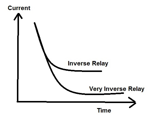
d) Very Inverse Relay:
Very Inverse Relay is one in which the range of operation is inverse with respect to fault current over a wide range. This happens so as the CT saturation occurs at a later stage but as soon as CT saturation occur there will not be any flux change and hence the current output of CT will become zero and hence the time of operation will nearly become constant.
e) Extremely Inverse Relay:
Extremely Inverse Relay is one in which CT saturation occur still at a later stage as compared with Very Inverse Relay and hence the characteristic remain inverse up to a larger range of fault current. The equation describing the Extremely Inverse Relay is I2t = K where I is operating current and t is time of operation of the Relay.
IEC (International Electrotechnical Commission) Standard Curve for Inverse Relays:
As per IEC, the time of operation of any Inverse relay can be calculated from the formula given below.
Here,
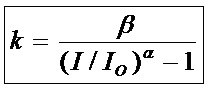
K = Time of actuation
α, β = Constant which depends on the type of Relay
I = Fault Current
I0 = Pick-up current
Value of α and β for different types of Relay:
|
Sr. No.
|
Type of Relay
|
α
|
β
|
|
1)
|
Inverse time over current Relay / IDMT
|
0.02
|
0.14
|
|
2)
|
Very Inverse Relay
|
1.00
|
13.5
|
|
3)
|
Extremely Inverse Relay
|
2.00
|
80.00
|
Example: Suppose the pick-up current for an IDMT relay is set at 0.8 A and the fault current is 80 A then the time of actuation can be calculated as
K = 0.14/[ (80/0.8)0.02– 1]
= 0.14/[1.096-1] = 0.14/0.096 = 1.45 seconds
Simplest way to understand the over current relay. Simple and clear in a nutshell.
Thanks a lot!
Thank you Shruti!
plz explain about synchronizing relay principle and operation
Sure, I will post on this. Thank you for suggesting such a good topic.
Please fuuly explain about IDMT Curve Characteristics
What do you want to know regarding IDMT?
thanks a lot, understand it now, can you please continue discussion up to log log graph?