Why Directional Relay?
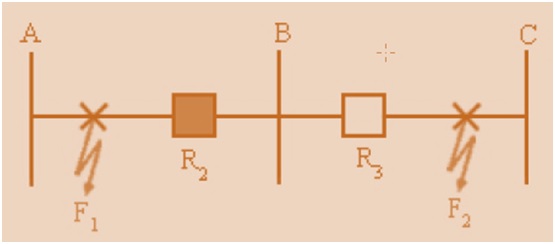
For understanding the need of Directional Relay we consider a power system as shown in figure below.

For fault at F1, Relay R2 is supposed to pick-up and operate the circuit breaker. Similarly for fault at F2, Relay R1 shall operate to isolate the faulty section from the healthy section. Now suppose fault occurs at F2, it may happen so that Relay R2 operate before the operation of Relay R1 as the set pick-up value for both the Relay is same and both Relay see the same fault current. As Relay R2 is operating here hence the power supply to the load from Source B is interrupted even when there is no fault in that section. To avoid such scenario what can be done?
Can we provide time graded protection here? No, we can’t provide time graded protection here as if there is fault at F1 then because of time grading Relay R2 will take more time to operate because of intentional time delay provided.
So what could be the solution? We may arrange something such that Relay R1 only operate if the fault is at F2 or toward Source A and likewise Relay R2 operates if the fault is at F1 or toward source B. This provision is Directional Feature as we are assigning a direction in which the Relay has to operate.
But how can we provide this directional feature to a Relay? Which electrical quantities need to be used for this?
For answering this, suppose a system as shown below.

Suppose a fault occurs at F1. The fault current is flowing in the direction of I1. The bus voltage is measured using a PT which is Vp here. The CT secondary and PT secondary is connected to the Relay R2 Operating and Polarizing Coil respectively. Will explain Polarizing Coil latter in this section, be patient till then.
As the fault is at F1, the fault current I1will lag behind the reference voltage Vp. Now if the fault is at F2, the direction of fault current through the CT will change by 180 degree and therefore the CT secondary current will also change its direction by 180 degree and hence the fault current in this case will lead the reference voltage Vp (saying reference voltage assuming that Vp remain unchanged).
To summarize, if the fault is at F1 then current is lagging Vp and if fault is at F2, current is leading Vp. We can use this concept to provide directional feature in the Relay. We can set in the Relay that if I1 laggs Vp then only it should operate for both Relays R2 and R3, thereby eliminating the problem of actuation of R3 for fault at F1.
Thus, if we measure the bus voltage phasor Vp and compute the phase angle of relay current with respect to bus voltage, then we can use the following logic to provide selectivity. If the relay ‘detects fault’ and current lags VR (= Vp), then permit relay tripping. If the relay ‘detects fault’ and current leads VR (= Vp), then inhibit the relay tripping. The ‘discrimination principle’ based on phase angle comparison between a set of phasors, one of which is used as reference is called ‘Directional Discrimination Principle’. Relays with this principle are called directional relays.

Any Relay can be made directional by incorporating directional element in it. For example we can use directional element in over-current relay to make it Directional Over-current Relay. This Relay will actuate if the angle between the fault current and Reference Voltage is satisfied AND over-current element picks up.
How Directional Relays are designed?
The torque developed by a directional unit is given as
T = VICos(Ɵ-Ƭ) – K
Where,
V = RMS value of voltage fed to the voltage coil of Relay
I = RMS value of current fed to the current coil of the Relay
Ɵ = Angle between V and I
Ƭ = Maximum torque angle, fixed by design (How fixed?)
|
As we know that Torque produced by a Relay = K1Ø1Ø2Sinξ, where ξ is the angle between Ø1 and Ø2. K1 is some constant. Therefore maximum torque will be produced when ξ = π/2
The angle ξ is developed because of Shaded Pole in the Relay so how much lagging flux will be developed by Shaded Pole depends upon the construction and design. Therefore the maximum Torque angle ξ is fixed by design.
|
The phasor diagram for directional over-current relay is shown below.
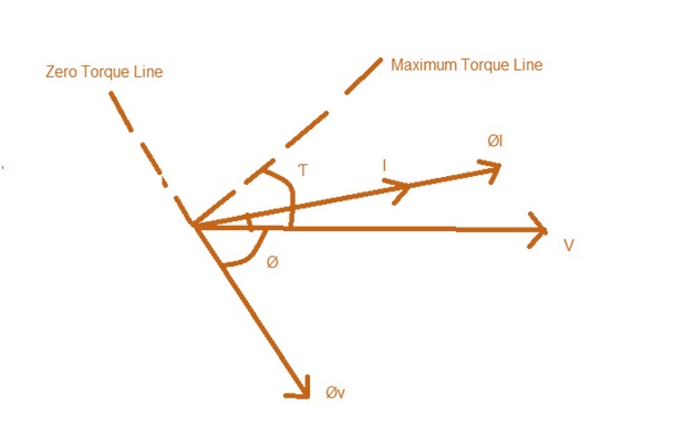
Here, Øv is the flux created by Voltage Coil which lags behind the Voltage by around 70 to 80 degree. ØI is the flux created by current coil. The net torque is produced by the interaction of Øv and ØI. The torque will be zero if the angle between Øv and ØI is 180 degree which is as shown in the phasor above. This is called Zero Torque Line. Also, if the angle between Øv and ØI is 90 degree then the Torque will be maximum which is shown by dotted line in the above phasor which is called Maximum Torque Line and the angle Ƭ is called Maximum Torque Angle or Relay Characteristics Angle (RCA). Here it is to be noted that V is assumed fixed and hence reference phasor. This reference phasor is called Polarizing quantity.
Now, as V is unchanged hence for the production of net torque for directional Relay,
VICos(Ɵ-Ƭ) – K>0
Assume k to be negligible, actually K is restrain torque because of spring and friction.
VICos(Ɵ-Ƭ)>0
Ɵ-Ƭ> +(-)π/2
Ɵ> Ƭ+(-)π/2
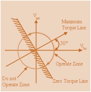
This equation can be represented in polar form as shown below.
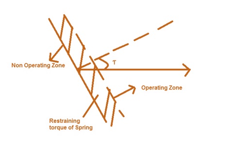
Carefully observe the zone where the Relay operates and the zone where it is not operating. Therefore, it is clear that the Relay operates in between the Zero Torque Line on both side of Maximum Torque Line. Observe that Maximum Torque Line and Zero Torque Line are perpendicular to each other.
Now, how to select reference Voltage Phasor?
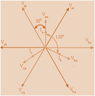
Vector diagram and relationship between different phasors are shown above.
Here, Vbc is perpendicular to the Van. Therefore it is better to take Vbc as reference phasor. We take the Maximum Torque Line at an angle of 30° with Vbc. As Zero Torque Line is perpendicular to the Maximum Torque Line, hence it is drawn as shown in figure below. We need to check whether the Relay will operate for Line to Line and Phase Phase to Line fault for this assumed reference Phasor. It does operate, which is described below.
Now consider a line fault involving phase ‘a’ and ‘b’. Then, using 3-phase line model we get,
Va – Vf = ZsIa + Zm(-Ia) = (Zs – Zm) Ia = Z1Ia
Similarly,
Vb- Vf = ZsIb + ZmIa = – (Zs – Zm) Ia = – Z1Ia
So, Va- Vb = 2Z1 Ia
Ia = (Va- Vb)/ 2Z1
If for simplicity we assume Z to be purely reactive, then from below figure we get that If ab will be at an angle of 60 degrees lagging to Van. Thus, unit with Vbc as reference phasor will pick-up on both 3-phase fault and L-L fault.
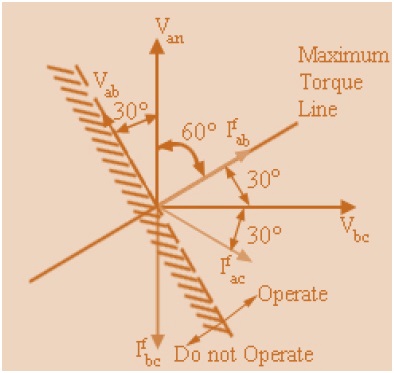
For a L-L fault involving phases ‘a’ and ‘c’ , Vac lags Van. Assuming purely reactive circuit, the phase current Ia will lag Vbc by . As seen in the figure, Iac will be again in the operate region and the directional unit will pickup. Thus, this unit (lead with Vbc as reference phasor) will pickup for all phase faults involving phase ‘a’. In contrast, for L-L fault involving phases ‘b’ and ‘c’, Ibc will lag Vbc by 90º. Hence, it will lie outside the tripping region of the directional unit. Therefore, directional unit will not pick up.
To summarize, the key feature in obtaining directional discrimination is the placement of zero torque line which separates the R-X plane into two regions viz. operate and do not operate. It is apparent that in numerical relays, this placement is quite flexible and can be specified with respect to any one reference voltage phasor. This placement can be made programmable.
Hope it might help you. Thank you! Waiting for your comment…
Relay always ENERGIZES, relay contacts "pick up". It's technically incorrect to use the term "pick up" when actually relay with its coils energizes.
Here the term Pick-up means it's pick up value at which it's coil gets energized and makes contact. Thank you for sharing your knowledge!
Dear All,
The pick up means, the rotating disc starts moving at the Pick-up current value. till then there will be a continuous torque on the disc but do not move. When it moves this is nothing but PICKING UP the disc.
HOPE MY EXPLANATION is appropriate.
Raj KUMAR
nice explanation,
i have one doubt. if fault f1 occurs, how you say it lags vp. why f1 fault current lags vp and f2 fault current lead vp. please reply
Carefully observe the direction of fault current for both the faults,the direction of current for both the fault will be opposite as sensed by the relay, therefore in one case current lags while in other it leads. Hope you got the point. Thank you for asking.
hi
Why directional overcurrent settings varies depend upon voltage rating of the system…??? For medium.voltage 45degree30degre and high voltage system 90 degree pls explain
Very interesting and useful information.
so in case of Phase B-C fault phase directional relay not operated as per your mentioned above line Ibc is in non operating region??
kindly elaborate.
For L-L fault involving phases ‘b’ and ‘c’, Ibc will lag Vbc by 90º. Hence, it will lie outside the tripping region of the directional unit. Therefore, directional unit will not pick up.
great easy to understand thank you.
Yes, it is very helpful. Can it explained with some more practical examples by considering Micom relay P127,P443 relay.
Can you explain the directional Earth Fault Protection on transmission lines.
In MiCom Relay, you just need to enable directional feature and set a characteristic angle.
For deciding the operating zone whether we shall take 3V0 as polarizing reference or Vab,Vbc or Vca as polarizing quantity.suppose on a transmission line a LG fault occurred in phase C , and Max. Torque angle is 45 deg. Then what is the polarizing voltage and what is the region of Operation of the relay
understood what is relay characteristics angle.