Reactance is defined an electrical quantity due to which alternating current is opposed by inductor or capacitor or combination of both of them in a circuit. Impedance is the net opposing factor to alternating current. Reactance may also be called impedance offered either by inductor or capacitor. Reactance is denoted by X and impedance by Z. In this article, we will discuss reactance and impedance in detail.
What is Reactance?
Reactance is the opposition offered to flow of alternating current. This opposition may either be due to inductor (L) and or capacitor (C). The value of reactance due to inductor having inductance L is ωL whereas its value is (1/ωC) for capacitor having capacitance C.
Explanation of Reactance:
Let us consider a circuit for better understanding. In the circuit, an inductor with inductance L Henry is connected to an alternating source V = VmSinωt. Here, ω is the angular frequency in radian/sec. ω = 2πf where f is supply frequency in Hz. The current in the circuit is I.
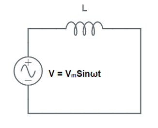
The current I flowing through the circuit is equal to [VmSin(ωt – π/2) / (ωL)]. Hence, maximum value of this current is given as
Im = (Vm/ ωL)
= (Vm/ XL)
where XL = ωL
Carefully observe the above expression of current and compare it with Ohm’ Law (I = V/R). You will notice that, here XL is doing the job of R. That is, XL = ωL is opposing the flow of current just like a resistance does. This is the reason; it is called reactance. Since it is offered by an inductor, it called inductive reactance and indicated by symbol XL.
Let us now consider another circuit comprising of capacitor and an alternating source as shown below.

The current through the circuit is equal to (VmωC)Sin(ωt+π/2). Therefore, maximum value of current will take place when Sin(ωt+π/2) = 1 and this value is given as below.
Im = Vm/ (1/ωC)
= Vm/ XC
On comparing the above value of current Im with Ohm’s Law (I = V/R), it is clear that XC is opposing the flow of current and acts as resistance. This XC = (1/ωC) is called capacitive reactance.
What is Impedance?
Impedance in alternating current circuit is defined as the net opposing factor to flow of current. This opposition may be due to Resistance & Inductance or Resistance & Capacitance or Resistance, Inductance and Capacitance. It is denoted by symbol Z. Z is often expressed as Z = R+jX where X is the reactance.
Explanation of Impedance:
To have a crystal-clear concept of impedance, let us consider a circuit shown below. In this circuit, a pure resistance R and a pure inductive coil with inductance L are connected in series.

Let, V = rms value of applied voltage
I = rms value of circuit current
VR = Voltage drop across R
VL = Voltage drop across coil
Assume circuit current to be the reference phasor. The voltage drop in resistance will be in phase with current I. However, the voltage drop in inductive coil will lead the current I by 90°. These voltage drops are shown in voltage triangle OAB.

Vector OA, AB and OB represents the voltage drop in resistance (VR), inductive voltage drop (VL) and the supply voltage (V) respectively. The supply voltage (V) is the hypotenuse of this voltage triangle. Therefore, the supply voltage may be calculated as below.

The quantity Z is the magnitude impedance of alternating current circuit. From the voltage triangle, the supply voltage may also be written using j operator. This is shown below.
V = (IR) + j(IXL)
I = V / (R+jXL)
= V/Z
Thus, impedance Z = R+jX. Thus, impedance is a complex quantity. The angle which the Z makes with reference phasor is calculated from tanƟ = (X/R).