As we know that the total energy consumed by a load is given as,
E = P.t where P = Power and t = time
But as the load current may not be constant rather it will vary as per the loading therefore we need to use integration for calculating the total energy consumed by load.
Thus we need an integrating instrument which can measure and record the energy consumed by the load under varying load condition. The simplest such instrument is Single Phase Induction Type Energy Meter.
Construction:
There are four main parts of the operating mechanism of Single Phase Induction Type
- Energy Meter.
- Driving System
- Moving System
- Braking System
- Registering System
Driving system:
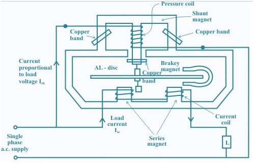
The driving system of the meter consists of two electro-magnets. The core of these electromagnets is made up of silicon steel laminations. The load current excites the coil of one of the electromagnets. This coil is called the current coil.
The coil of second electromagnet is connected across the supply and, therefore, carries a current proportional to the supply voltage. This coil is called the pressure coil. The two electromagnets are known as series and shunt magnets respectively as shown in figure.
Copper shading bands are provided on the central limb for development of phase splitting. The position of these bands is adjustable. The function of these bands is to bring the flux produced by the shunt magnet exactly in quadrature with the applied voltage.
Moving System:
- This consists of an aluminum disc mounted on a light alloy shaft.
- This disc is positioned in the air gap between series and shunt magnets.
- The upper bearing of the rotor (moving system) is a steel pin located in a hole in the bearing cap fixed to the top of the shaft.
- The rotor runs on a hardened steel pivot, screwed to the foot of the shaft.
- A jewel bearing supports the pivot.
- A pinion engages the shaft with the counting or registering mechanism.
Braking System:
A permanent magnet positioned near the edge of the aluminium disc forms the braking system. The aluminium disc moves in the field of this magnet and thus provides a braking torque because of flow of eddy current in the aluminium disc. The position of the permanent magnet is adjustable, and therefore braking torque can be adjusted by shifting the permanent magnet to different radial positions.

Registering Mechanism:
The function of a registering or counting mechanism is to record continuously a number, which is proportional to the revolutions made by the moving system. By a suitable system, a train of reduction gears the pinion on the rotor shaft drives a series of five or six pointers. These rotate on round dials, which are marked with ten equal divisions.
Operating Mechanism:
When the energy meter is connected in the circuit, the current coil carries the load current and the pressure coil carries the current proportional to the supply voltage. The magnetic field produced by the SERIES magnet i.e. series coil is in phase with the line current & the magnetic field produced by the shunt magnet i.e. pressure coil is in quadrature with the applied voltage since the coil is highly inductive. Thus, a phase difference exists between the fluxes produced by the two coils. This produces a driving torque and, thus, disc starts rotating. The number of revolutions made by the disc depends upon the energy passing through the meter. The spindle is geared to the recording mechanism so that electrical energy consumed in the circuit is directly registered in KWh. The speed of the disc is adjusted by adjusting the position of the breaking magnet. For example, if the energy meter registers less energy than the energy actually consumed in the circuit, then the speed of disc has to be increased which is obtained by shifting the magnet nearer to the centre of the Disc and vice-versa.
At constant angular speed the power is proportional to the angular speed in r.p.s.
Let K be the meter constant of energy meter, which is the number of revolution per KWh energy consumption. When connected to measure energy, if disc makes R number of revolution in t seconds. Then the reading of energy meter is
E = R/K
Let kW= Power in Kilowatt from wattmeter reading.
R= No. of revolution made by disc in t sec.
K = Number of Revolution/kWh
Hope it might help you. Thank you!
How is driving torque produced . Can u epls explain in more detail.