Power Line Carrier Communication, often called PLCC, is used for speech data transmission as well as protection of Transmission Lines. Carrier current used for Power Line carrier Communication has a frequency range of 80 to 500 kHz. PLCC is mainly for telemetry and telecontrol in modern electrical Power System.

Power Line Carrier Communication is used for the Carrier Tripping and Direct Tripping in case of Distance Protection. For detail of how does Distance protection relay sends and receives carrier signal, read Distance Protection philosophy.
Whenever there is a fault in the line, it is very much important to isolate the fault. Merely tripping of breaker at one end of line cannot isolate the fault. Breaker at the other end of line should also open. Let us consider a simple diagram as shown below.
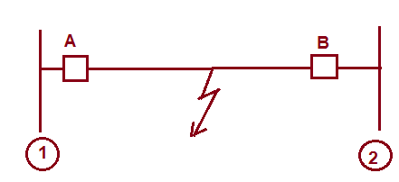
In case of fault, breaker A and B should open. Let us assume that, the fault is being sensed by relay at station 1. This relay should issue trip command to breaker A and send trip signal to the remote end. This trip signal to remote end is called Direct Trip(DT) signal. On reception of DT signal, master trip relay at Remote station 2 actuates which in turn actuates breaker B. This trip signal i.e. DT signal is sent via PLCC. Apart from DT signal, carrier signal is also sent via PLCC Panel. This signal is used for Auto Reclosure.
For communication between the two substations, each end of transmission line is provided with identical PLCC equipment consisting of equipment:
- Transmitters and Receivers
- Hybrids and Filters
- Line Matching Unit
- Wave Traps
- Power Amplifier
- Coupling Capacitors orCapacitive Voltage Transformer
PLCC Scheme:
The output of PLCC goes to Coupling Capacitor famously known as Capacitive Voltage Transformer and then to transmission line and travels to another end where it is received through Capacitive Voltage Transformer and inputted to relay and control panel at that end.

As the frequency of carrier signal is high, the impedance offered by the CVT = 1/wC will be low and the carrier signal travelling on Transmission Line will be bypassed by the CVT, therefore the carrier signal is received or sent through the CVT (HF point is given on the CVT where PLCC is connected through the Fiber Optic FO Cable.)
Wave Trap is provided in the line after the CVT (If we see from Transmission line side then CVT will come first and then CVT will come.). Wave Trap is nothing but a Choke Coil which chokes out high frequency carrier signal, as the impedance offered by inductor = wL will be high which will not allow the high frequency carrier signal to enter into the substation.
Main Components of PLCC:
Following are the main components of PLCC.
Coupling Capacitor:
Coupling capacitor or Capacitive Voltage Transformer connects the carrier equipment to the transmission line. The coupling capacitor’s capacitance is of such a value that it offers low impedance to carrier frequency (1/ωC) but high impedance to power frequency (50 Hz).
Thus coupling capacitor allows carrier frequency signal to enter the carrier equipment. To decrease the impedance further and make the circuit purely resistive so that there is no reactive power in the circuit, low impedance is connected in series with coupling capacitor to form resonance at carrier frequency.
Wave Trap:
Wave Trap is provided in the line after the CVT (If we see from Transmission line side then CVT will come first and then CVT will come.). Wave Trap is nothing but a Choke Coil which chokes out high frequency carrier signal, as the impedance offered by inductor = wL will be high which will not allow the high frequency carrier signal to enter into the substation.

Transmitters and Receivers:
The carrier Transmitters and Receivers are usually mounted in a rack or cabinet in the control room, and the line tuner is out in the switchyard. Thus there is a large distance between the equipment and the tuner, and the connection between the two is made using a coaxial cable Fiber Optical (FO) Cable.
The coaxial cable provides shielding so that noise cannot get into the cable and cause interference. The coaxial cable is connected to the line tuner which must be mounted at the base of the coupling capacitor. If there is more than one transmitter involved per terminal the signal must go through isolation circuits, typically hybrids, before connection to the line tuner.
Hybrids and Filters:
The purpose of the hybrid circuits is to enable the connection of two or more transmitters together on one coaxial cable without causing intermodulation distortion due to the signal from one transmitter affecting the output stages of the other transmitter. Hybrids may also be required between transmitters and receivers, depending on the application.
Line Matching Unit LMU:
LMU is a composite unit consisting of Drain Coil, Isolation transformer with Lightning Arrester on its both the sides, a Tuning Device and an earth switch. Tuning Device is the combination of R-L-C circuits which act as filter circuit. LMU is also known as Coupling Device. Together with coupling capacitor, LMU serves the purpose of connecting Audio/Radio frequency signals to PLCC terminal and protection of the PLCC unit from the over voltages caused due to transients on power system.

Application of PLCC:
PLCC in modern electrical power system substation is mainly used for following purpose:
Thanks
Useful information…..
Really great blog!
Bookmark this already..
very useful and conceptual information.