Speed control of BLDC motor is essential for making the motor work at desired rate. Speed of a brushless dc motor can be controlled by controlling the input dc voltage / current. The higher the voltage more is the speed.

The control algorithm must provide three things:
- PWM voltage to control the motor speed
- Mechanism to commutate the motor
- Method to estimate the rotor position using the back-EMF or Hall Sensors
Pulse-width modulation is used to apply a variable voltage to the motor windings. The effective voltage is proportional to the PWM duty cycle. When properly commutated, the torque-speed characteristics of the BLDC motor are identical to a dc motor. The variable voltage can be used to control the speed of the motor and the available torque.
The commutation of the power transistors energizes the appropriate windings in the stator to provide optimum torque generation depending on the rotor position. In a BLDC motor, the MCU must know the position of the rotor and commutate at the appropriate time.
The speed control can be closed loop or open loop speed control.
Open Loop Speed Control – It involves simply controlling the dc voltage applied to motor terminals by chopping the dc voltage. However this results in some form of current limiting.
Closed Loop Speed control – It involves controlling the input supply voltage through the speed feedback from the motor. Thus the supply voltage is controlled depending on the error signal. The closed loop speed control consists of three basic components.
A PWM circuit to generate the required pwm pulses. It can be either a microcontroller or a timer IC.
A sensing device to sense the actual motor speed. It can be a hall effect sensor, a infrared sensor or a optical encoder.
Trapezoidal Commutation of BLDC Motor:
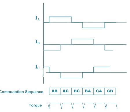
One of the simplest methods of control for dc brushless motors uses what is termed Trapezoidal commutation. In this scheme, current is controlled through motor terminals one pair at a time, with the third motor terminal always electrically disconnected from the source of power.
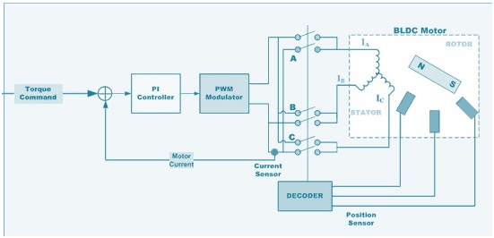
Three Hall devices embedded in the motor are usually used to provide digital signals which measure rotor position within 60 degree sectors and provide this information to the motor controller. Because at any time, the currents in two of the windings are equal in magnitude and the third is zero, this method can only produce current space vectors having one of six different directions. As the motor turns, the current to the motor terminals is electrically switched (commutated) every 60 degrees of rotation so that the current space vector is always within the nearest 30 degrees of the quadrature direction. The current waveform for each winding is therefore a staircase from zero, to positive current, to zero, and then to negative current. This produces a current space vector that approximates smooth rotation as it steps among six distinct directions as the rotor turns.
In motor applications such as air conditioners and refrigerators use of Hall-Effect sensors is not a viable option. Back-EMF sensors that sense the back EMF in the unconnected winding can be used to achieve the same results.
The trapezoidal-current drive systems are popular because of the simplicity of their control circuits but suffer from a torque ripple problem during commutation.
Sinusoidal Commutation for BDLC Motors:
Trapezoidal commutation is inadequate to provide smooth and precise motor control of brushless dc motors, particularly at low speeds. Sinusoidal commutation solves this problem.
This is because the torque produced in a three phase brushless motor (with a sine wave back-EMF) is defined by the following equation:
Shaft Torque = Kt [IRSin(δ) + IY Sin(δ +120) + IB Sin(δ o+240)]
where:
δ is the electrical angle of the shaft,
Kt is the torque constant of the motor and
IR, IYand IB are the phase currents.
Assuming phase currents sinusoidal: IR = I0Sinδ; IY = I0Sin (δ +120); IB = I0Sin (δ +240)
Therefore,
Shaft Torque = 1.5I0xKt
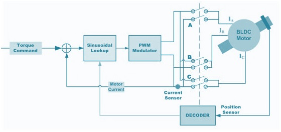
Sinusoidal commutated brushless motor controllers attempt to drive the three motor windings with three currents that vary smoothly and sinusoidally as the motor turns. The relative phases of these currents are chosen so that they should result in a smoothly rotating current space vector that is always in the quadrature direction with respect to the rotor and has constant magnitude. This eliminates the torque ripple and commutation spikes associated with trapezoidal commutation.
Sinusoidal commutation results in smoothness of control that is generally unachievable with trapezoidal commutation. However, while it is very effective at low motor speeds, it tends to fall apart at high motor speeds. This is because as speed goes up the current loop controllers must track a sinusoidal signal of increasing frequency. At the same time they must overcome the motor back-EMF that also increases in amplitude and frequency as speed goes up.
This degradation continues as speed increases. At some point motor current phase shift crosses through 90 degrees. When this happens torque is reduced to zero. With sinusoidal commutation, speeds above this point result in negative torque and are therefore not achievable.
Is a BLDC Motor Bidirectional?
Yes, because BLDC motors work using electronic commutation. Electronic commutation means that the magnetic field, to which the rotor tends to align, is rotated electronically.
Thank you! Please add some new points by writing in comment box as it will help more.
With Programmable BLDC motor controllers(24V-60V), what happens with a 24V motor if the controller is supplied 36V but motor voltage is set to 24V in configuration?
nice presentation
Can we control the speed of BLDC motor by changing frequency of the pwm sinal?
kindly add speed control ,torque control,voltage control also in the phase of differences.Along with trapezoidal,sinusoidal,FOC also ….
Thank you