What is Parallel Resonance Circuit?
Parallel resonant circuit is a generic term which consists of resistor, inductor as well as a capacitor in parallel connection.
At resonance there will be a large circulating current between the inductor and the capacitor due to the energy of the oscillations, and then parallel circuits produce current resonance.
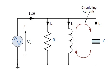
A parallel resonant circuit stores the circuit energy in the magnetic field of the inductor and the electric field of the capacitor. This energy is constantly being transferred back and forth between the inductor and the capacitor which results in zero current therefore the current drawn from the supply is equal to current flowing in Resistor i.e. IR.
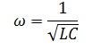
As at Resonance, XL= XC therefore the impedance of circuit = R
It shall be observed that at resonance the parallel circuit produces the same equation as for the series resonance circuit. Therefore, it makes no difference if the inductor or capacitor is connected in parallel or series. Also at resonance the parallel LC circuit acts like an open circuit with the circuit current being determined by the resistor, R only.
Impedance in a Parallel Resonance Circuit:

Current in a Parallel Resonance Circuit:
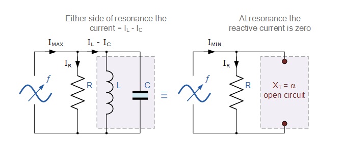
At Resonance, X = R and maximum impedance in Resonance as clear from the impedance-frequency curve, hence current at Resonance will be minimum and equal to Vs / R.
The frequency response curve of a parallel resonance circuit shows that the magnitude of the current is a function of frequency and plotting this onto a graph shows us that the response starts at its maximum value, reaches its minimum value at the resonance frequency when IMIN = IR and then increases again to maximum as ƒ becomes infinite.
The result of this is that the magnitude of the current flowing through the inductor, L and the capacitor, C circuit can become many times larger than the supply current, even at resonance but as they are equal and at opposition ( 180o out-of-phase ) they effectively cancel each other out.
As a parallel resonance circuit only functions on resonant frequency, this type of circuit is also known as a Rejecter Circuit because at resonance, the impedance of the circuit is at its maximum thereby suppressing or rejecting the current whose frequency is equal to its resonant frequency. The effect of resonance in a parallel circuit is also called Current Resonance.
Bandwidth & Selectivity of a Parallel Resonance Circuit:
The upper and lower cut-off frequencies given as: ƒupper and ƒlower respectively denote the half-power frequencies where the power dissipated in the circuit is half of the full power dissipated at the resonant frequency i.e. ( I2R )/2 which gives us the same -3dB points at a current value that is equal to 70.7% of its maximum resonant value, 0.707 x I 2 R.
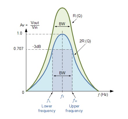
If the resonant frequency remains constant, an increase in the quality factor, Q will cause a decrease in the bandwidth and likewise, a decrease in the quality factor will cause an increase in the bandwidth as defined as
BW = ƒr /Q or BW = ƒupper – ƒlower
Also changing the ratio between the inductor, L and the capacitor, C, or the value of the resistance, R the bandwidth and therefore the frequency response of the circuit will be changed for a fixed resonant frequency. This technique is used extensively in tuning circuits for radio and television transmitters and receivers.
The selectivity or Q-factor for a parallel resonance circuit is generally defined as the ratio of the circulating branch currents to the supply current and is given as
Quality Factor Q = R/(2πfL)
= 2πfCR
It should be mind that the Q-factor of a parallel resonance circuit is the inverse of the expression for the Q-factor of the series circuit. Also in series resonance circuits the Q-factor gives the voltage magnification of the circuit, whereas in a parallel circuit it gives the current magnification.