We know that Relay is a switch which senses fault in a system and once fault is sensed by the Relay, it issues trip command to the Circuit Breaker, CB to isolate the faulty section of the network from the healthy section.
The Relay detects the abnormal condition by continuously monitoring electrical quantities which are different for healthy and faulty condition. The electrical quantities which may change during fault condition are voltage, current, frequency and phase angle. If one or more of the above electrical quantities change, that signals the presence, type and location of the fault to the Relay. After detecting the fault condition, Relay pick-up, its contact will change from NO to NC or vice versa. So we can wire up a particular kind of Relay contact to Breaker tripping circuit. So whenever, the Relay picks up, the tripping of Breaker will take place.
Relay coil when picked up will change its contact status. Let us say Relay Normally Open (NO) contact is wired to the Breaker Trip Coil Circuit. Therefore when the Relay coil is in de-energized state, the circuit of Trip Coil of CB is not complete and hence no tripping of the CB. During fault condition as the current through the Relay coil exceeds the pick-up value, the Relay coil will get actuated which in turn will force its contact to change over i.e. NO contact will change to Normally Close (NC) thereby closing the Trip Coil circuit of the Breaker.
Relays may be fitted with a variety of contact systems for providing electrical outputs for tripping and remote indication purposes. The most common types of relay Output contacts are as follows:
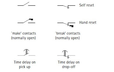
a) Self-reset Type. The contacts remain in the operated condition only while the controlling quantity is applied, returning to their original condition when it is removed
b) Hand or Electrical Reset. These contacts remain in the operated condition after the controlling quantity is removed. They can be reset either by hand or by an auxiliary electromagnetic element.
The majority of protection relay elements have self-reset contact systems, which, if so desired, can be modified to provide hand reset output contacts by the use of auxiliary elements. Hand or electrically reset relays are used when it is necessary to maintain a signal or lockout condition. Contacts are generally shown on engineering diagrams in the position corresponding to the un-operated or de-energized condition, regardless of the continuous service condition of the equipment. For example, an under-voltage relay, which is continually energized in normal circumstances, would still be shown in the de-energized condition.
A ‘make’ contact is one that closes when the relay picks up, whereas a ‘break’ contact is one that is closed when the relay is de-energized and opens when the relay picks up. Examples of these conventions and variations are shown in figure below.

Please explain about various types of auxiliary relays with example
Definitely I will post on the suggested topic. You are requested to kindly subscribe so that you may get the update of latest post.
I LIKE YOUR CONCEPTS PLEASE SEND IT IN DETAILS
Thank you! Please share if you like it.