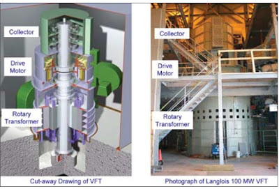
Variable Frequency Transformer or simply VFT is quite a new technology to connect two asynchronous Grids. Asynchronous Grids mean two power systems operating at two different frequencies. The world’s first VFT was installed and commissioned in the year of 2004 at Hydro- Quebec’s Langlois substation, where it is used to exchange up to 100 MW of power between the asynchronous power grids of Quebec (Canada) and New York (USA).
First thing to note here that though the name suggests it to be Transformer but construction wise it is like a Slip Ring Induction Motor. The basic concept behind the VFT is a rotary transformer with three phase windings on both rotor and stator. A motor and drive system are used to adjust the rotational position of the rotor relative to the stator, thereby controlling the magnitude and direction of the power flowing through the VFT. VFT is a controlled bi-directional device allowing flow of power in both directions i.e. from one Grid to another and vice versa. Mind that VFT is serving the same purpose as a Back to Back HVDC system.
The Variable Frequency Transformer consists of a stator which is much like the stator of a hydro generator. There are laminations of steel stacked inside a stator frame. Windings are configured into a three phase four pole arrangement. Stator is connected to one power system via a Step-up Transformer. The rotor is constructed in the same manner as the stator. The rotor also contains three phase four pole windings. One grid is connected to the stator windings, while the other grid is connected to the rotor. The net effect is that a circular transformer has been produced, with the windings separated by an air gap.
In order to make connection to the rotor and still allow the rotor to turn freely, a slip ring arrangement is necessary. The VFT contains a device known as the collector. The collector consists of three phases of brushes and large copper slip rings. The number and size of the elements of the collector are such that the full rating of the machine current can be transferred continuously through the full range of speeds in either direction, including zero speed. Also on the shaft of the VFT a DC drive motor is connected. This motor is used to align the rotor with respect to the stator and maintain the rotation necessary to bridge the difference in the frequency of the two grids. Through the slip ring arrangement, rotor of VFT is connected to another power system through a Step-up Transformer.
Working Principle of Variable Frequency Transformer:
As discussed earlier in the post Stator of VFT is connected to one Grid through Step-up Transformer and Rotor is connected to another Grid through Step-up Transformer. Now we will see how Power Transfer take place in such doubly fed machine i.e. VFT. For any AC system the equation of power flow
P = V1V2Sinδ / X
Where V1 and V2are voltages and δ is the angle between them.
Here in case of VFT, the voltage V1 is voltage of one Grid (say connected to Stator) and V2is voltage of another Grid (say connected to Rotor). As it is expected that both the Grid are operating at same voltage level and turn ratio of Step-up Transformer are also same, that means V1 = V2 = V (say). Thus the power flow equation for VFT will reduce to
P = V2Sinδ / X
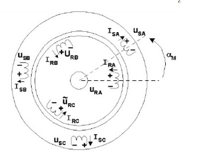
Thus δ is here variable quantity which we can change. Here comes the role of Drive Motor. The drive motor connected to the shaft of rotor just changes the angle δ by rotating the rotor. The angle introduced in the rotor with respect to the stator, by the torque motor, is proportional to the amount of torque (T) applied to the shaft. Therefore we can say that, power flow through a Variable Frequency Transformer i.e. VFT is directly proportional to torque applied by the drive motor.
A closed loop power regulator maintains power transfer equal to an operator set point. The regulator compares measured power with the set point, and adjusts motor torque as a function of power error. The power regulator is fast enough to respond to network disturbances and maintain stable power transfer.
In the figure above, suffix R stands for Rotor while suffix S for Stator. Phase angle difference between Stator voltage and Rotor voltage can easily be seen in the figure. The ability of the machine to rotate continuously is how the machine can bridge an asynchronous boundary. For example, assume a VFT connecting two asynchronous grids. For this example we shall call the Grids connected to VFT as Grid A and Grid B. When both grids are operating at exactly the same frequency, say 50.0 Hz, the VFT rotor will be stopped. If Grid A’s frequency increases slightly to 50.1 Hz, while Grid B’s frequency remains constant at 50.0 Hz, the rotor of the VFT will turn to allow for this difference. Because VFT is a four pole machine, in this case it will be rotating at 3 rpm [120 (50.1-50) / 4 = 3 ]. Consider now the condition where Grid A slows down to 49.9 Hz and Grid B is still at 50.0 Hz. The rotor will now be turning in the opposite direction at 3 rpm. The existing VFTs have a maximum operating speed of 90 rpm yielding a three hertz maximum frequency delta.
Like an ordinary transformer, the VFT has also magnetizing currents. Therefore we can classify the VFT as an induction machine. From a system level perspective, this means that the VFT consumes reactive power. In order to remain neutral to the grid from a reactive power point of view, shunt capacitors are supplied with a VFT to satisfy the machines own requirements. These are switched in and out by the VFT controls as needed. Additional shunt capacitors can be added to supply reactive power for either or both grids, if the application dictates that this is helpful to the systems.
Must watch this video taken from GE Reports. This video shows the use of VFT connecting New York (NY) and New Jersy (NJ) grids.
This is the basic concept of Variable Frequency Transformer. Hope you enjoyed the post. Thank you!


Really it is an awesome post. It helps me a lot to under the the VFT.
Thank you for the post…
Thank you! Keep visiting and share the post please.
well explained thanku sir