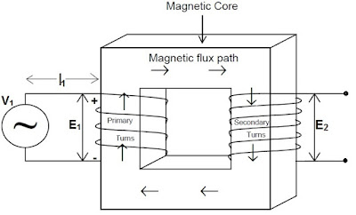
The working principle of Transformer is based on Faraday’s Law of Electromagnetic Induction. In a transformer, an alternating magnetic flux is generated in the core by the primary current. This alternating flux links with the secondary winding. As this flux linkage in secondary is time variant, an emf is induced across the terminals of secondary winding. This article outlines the working principle of Transformer along with concept of transformer action in detail.
Working Principle of Transformer:
Working Principle of Transformer is based on Faraday’s Law. Let us assume a Core Type Transformer as shown in figure below.
As shown in the figure, Primary winding of the Transformer is supplied with an alternating voltage source V1 while keeping the Secondary open. Due applied voltage V1, an alternating current Ie starts flowing through N1primary turns.
Thus alternating mmf of Primary = N1Ie
Because of this alternating mmf, an alternating flux is set up in the core of Transformer which links with the Primary as well as Secondary winding and as per Faraday’s Law of Electromagnetic Induction, an emf E1 & E2 are developed across the terminals of the Primary and Secondary winding.
This phenomenon is popularly known as Transformer action.
Now, we will go further and will have an insight of Two-winding Transformer. For the sake of clear understanding, first of all we consider an Ideal Transformer. An Ideal Transformer is one having the following characteristics:
- Negligible winding resistance.
- All the flux set up in the core links with the Secondary winding i.e. the flux is confined in the magnetic core of the Transformer.
- The core losses are negligible.
- Magnetization curve of core is linear.
Let the voltage V1 applied to the Primary of Transformer be sinusoidal. Thus the current Ie will also be sinusoidal and hence the primary mmf N1Ie must also be sinusoidal in nature. Note that flux Ø set up in the core of Transformer will be sinusoidal as the Primary mmf responsible for setting up the flux is sinusoidal.
Let,
Ø = ØmSinωt
Where Øm is the maximum value of magnetic flux in Weber (Wb) and ω = 2πf is the angular frequency in rad/sec.
Therefore,
Total flux linking through the Primary = N1xØ
= N1ØmSinωt
Hence,
Emf induced in the Primary e1= -d(N1Ø ) / dt
= -N1ωØmCosωt
= -N1ωØmSin(ωt – π/2)
Thus we see that the emf e1induced in the Primary winding is sinusoidal and lagging behind the flux Ø by 90°.
Maximum value of induced emf in Primary em = N1ωØm
So, em = 2πfN1Øm
Now, the RMS value of induced emf e in Primary winding E1,
E1 = 1.414xπfN1Øm
= 4.44fN1Øm ……………………….(1)
It must be noted and understand that the direction of emf induced the Primary winding will be in such a direction to oppose the cause i.e. applied voltage here in this case. As we have assumed the Transformer winding resistance negligible, so we can write for Primary circuit,
V1 = E1 …………………………(2)
Similarly, as the flux in the Transformer core is Ø, this flux will also link with the Secondary to induce an emf in the Secondary winding.
Flux linkage with the Secondary winding = N2Ø
=N2ØmSinωt
Hence,
Emf induced in the Secondary e2 = -d(N2ØmSinωt) / dt
= -N2ωØmCosωt
= -N2ωØmSin(ωt – π/2)
Maximum value of e2= N2ωØm
= 2πfN2Øm
So,
RMS value of emf E2induced in the Secondary winding
= 4.44N2fØm ……………….(3)
Thus we can write,
E1 / E2= N1 / N2 (From equation (1) & (3)) ………………(4)
E1 / N1= E2 / N2 = 4.44fØm
Which means,
Emf per turn in Primary = emf per turn in Secondary.
Consider the figure below.
As soon as switch S is closed, a current I2 starts flowing in the Secondary winding. The direction of this current will be in such a way to produce a magnetic flux opposite to the direction of working flux set up in the core. (This is as per the Lenze’s Law which says “Effect Opposes the Cause”). Thus the direction of current in the Secondary winding will be in anticlockwise direction; this is because current in anticlockwise direction will produce flux in upward direction in the core.
In this way we see that Secondary current tends to oppose the working flux. Any reduction in working flux Ø will cause a reduction in Primary emf E1 but as we have sen from from equation (2),
V1 = E1and V1 is constant.
This simply implies that working flux in the core of Transformer must be constant. To have a constant flux, Primary must draw an additional current I1’ from the source to compensate for the reduction caused by Secondary current.
Therefore, Compensating Primary mmf = Secondary mmf
N1I1’ = N2I2
Any change in the Secondary current is at once reflected by a corresponding automatic change in the Primary current so that core flux remains constant.
Here I1’ is called load component of current.
Thus Primary current I1= Ie+I1’
Ie is called the Magnetizing current as this much of current is required to set up working flux in the core when the Secondary terminal is open.
Normally the value of magnetizing current varies from 2-6% of full load current. If we neglect the magnetizing current then,
N1I1 = N2I2
N1 / N2= I2 / I1
Again as we have considered Transformer winding have negligible resistance so for Secondary circuit,
E2 = V2
Now, from equation (4),
E1 / E2= V1 / V2 = N1 / N2 = I2/ I1
Note that, concept of Transformer action is very important and one should know hoe to use and implement this concept.

