Voltage Regulation of Transformer is defined as change in magnitude of Secondary Terminal Voltage per unit Rated Secondary Terminal Voltage when load at a given Power Factor is reduced to zero while maintain the Primary Voltage constant.
Transformer Voltage Regulation = (E2– V2) / E2 in pu
= (E2– V2) x100 / E2 in percentage.
The change in magnitude of Secondary Terminal Voltage with loading of Transformer is because of Primary and Secondary leakage impedance. The magnitude of this change in voltage depends on the load current, load power factor, total leakage reactance and total resistance of Transformer.
As the consumer need their terminal voltage to be within a prescribed limit, the Voltage Regulation of a Distribution Transformer shall be less i.e. good. For better Voltage Regulation of a Distribution Transformer, it is quite important that their leakage impedance shall be less.
Calculation of Transformer Voltage Regulation:
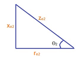
The Voltage Regulation of a Transformer can be obtained from its equivalent circuit model when referred to Primary or Secondary side. Figure below shows the equivalent circuit of a Transformer when referred to Secondary side and its phasor diagram for load of lagging power factor.
In the figure above,
re2 = Equivalent resistance referred to Secondary
xe2 = Equivalent reactance referred to Secondary
It can be seen from the above phasor diagram that,
E2 ≈ OC
= OA + AB + BC
But from the right angled Triangle ABE,
CosƟ2 = AB / AE
So, AE = ABCosƟ2
= I2re2CosƟ2
Similarly from the right angled Triangle DEF,
Therefore BC = EF = I2xe2SinƟ2
E2 = V2+ I2re2CosƟ2 +I2xe2SinƟ2
Hence,
(E2 – V2) = I2re2CosƟ2 +I2xe2SinƟ2
Now, per unit Voltage Regulation for any load current I2,
(E2 – V2) / E2 = I2re2CosƟ2 / E2+I2xe2SinƟ2 / E2
In case I2 is rated current then,
I2re2 / E2 = Voltage drop across re2 at rated current / Rated Voltage
= pu resistance drop
= εr ………………..(1)
Similarly,
I2xe2/ E2 = Voltage drop across reactance / Rated or Base Voltage
= pu reactance drop
= εx ………………………(2)
Therefore pu Voltage Regulation VR at rated current,
VR = εrCosƟ2 + εxSinƟ2
And percentage Voltage Regulation VR at rated current,
VR = (εrCosƟ2 + εxSinƟ2) x 100 %
The above calculation for Voltage Regulation has been carried out assuming lagging power factor load but for leading power factor load we only need to replace Ɵ2 by – Ɵ2. Therefore Voltage Regulation VR for leading power factor load for rated current will be as below.
VR = εrCosƟ2 – εxSinƟ2in pu.
= (εrCosƟ2 – εxSinƟ2) x 100 %
Now we will investigate some conditions based on Voltage Regulation which are very important.
Condition for Zero Voltage Regulation of Transformer:
As can be seen from the expression of Voltage Regulation, that VR varies as the Power factor of load is varied keeping load current constant. Thus for a particular Power Factor, we can get zero Voltage Regulation.
As VR = 0
εrCosƟ2+ εxSinƟ2 = 0
So,
tanƟ2 = – εr/ εx
From equation (1) and (2),
tanƟ2 = -re2 / xe2
Therefore Magnitude of Power Factor CosƟ2 = xe2 / ze2
Here negative sign in the value of tanƟ2 means that power factor of load is leading. Thus zero Voltage Regulation is achieved by leading load of power factor xe2 / ze2 and if we increase the power factor of load beyond this value then Voltage Regulation will become negative. Negative Voltage Regulation means that Secondary Terminal Voltage V2 is more than the no load generated EMF E2.
Condition for Maximum Voltage Regulation of Transformer:
For Maximum Voltage Regulation,
d(VR) / dƟ2 = 0 assuming load current constant.
Thus,
-εrSinƟ2+ εxCosƟ2 = 0
This implies that, tanƟ2= εx / εr
Thus, CosƟ2 = re2/ xe2
Here tanƟ2 is positive, which means that maximum Voltage Regulation occurs for lagging power factor load and at a power factor of re2 / xe2.
One important thing to note here that,
Leakage Impedance Angle = Ø
= Ɵ2
Thus we can say that, maximum Voltage Regulation occurs when load power factor is equal to leakage impedance angle.