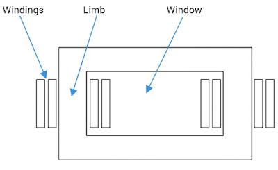
The area of the window and cross-sectional area of the limb are the main dimensions of a transformer; the product of which is directly proportional to the size and weight of the Transformer. Larger this product, bigger and heavier is the Transformer.
While designing a Transformer, the designer starts with an equation called the Output Equation of the Transformer. This equation relates the KVA rating of the Transformer and the dimensions of the Transformer.
The Output Equation for a single phase core type Transformer,
|
|
Where,
δ= Permissible current density (A/m2)
Q = Rating in KVA
f = Frequency
Ai = Cross sectional Area of Core
Bm = Maximum Flux Density in the Core
Aw = Window Area
Kw = Window Space Factor = Constant
Window Space Factor is defined as the Ratio of copper conductor Cross Setional Area to the Window Area.
In the Output Equation, the flux density depends on the type of material used to construct the Transformer Core; the current density depends on the type of cooling provided; and the window space factor is a constant. Therefore, the KVA rating is directly proportional to the product of frequency, area of the window and cross-sectional area of the limb. In other words, the KVA rating is directly proportional to the product of frequency and the size of the transformer.
For a given Transformer Rating, as the frequency increases, the product of window area and cross-sectional area of the limb decreases; this means the size of the Transformer core and the amount of iron required for the core decreases. Therefore as the frequency increases, the transformer becomes lighter and smaller in size.
An example where frequency is increased to reduce the size and weight of the transformer is in Aircraft where the Transformers are designed for 400 Hz.
I will discuss Transformer Design in detail in my next post. So be there and subscribe.
