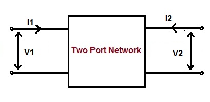
Z parameter is a factor by which input voltage and current & output voltage and current of two port network is related with. For any two port network, input voltage V1 and output voltage V2 can be expressed in terms of input current I1 and output current I2 respectively. It is also known as open circuit impedance parameter.
Z parameter in terms of input voltage V1 and output voltage V2 & input current I1 and output current I2 is given as below.
[ V ] = [ Z ] [ I ]
Where [Z] is impedance matrix, [V] and [I] are voltage and current matrix.
Therefore, in matrix form the input and output voltage and current can be represented as below.

Need of Z Parameter:
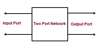
Any electrical network can be represented by a black box as we may not know the internal detail of the network. In order to connect this box with other network, it must have to have terminals. If it has two pairs of terminals for external connection, it is known as two port network or four terminal network. One pair of terminal is called input port while the other port is called output port. Driving source is connected to input port. Figure below shows the diagrammatic representation of a two port network.

To analyse the behaviour of this black box, we need to known the relationship between the input and output quantities. Z parameter gives us this relationship.
Calculation of Z Parameter:
Let us consider a two port network as shown in figure below.

As per the definition,
V1 = Z11I1 + Z12I2 ……(1)
V2 = Z21I1 + Z22I2 …….(2)
Assuming the output of the two port network to be open, therefore
I2 = 0
Now putting I2 = 0 in (1), we get
V1 = Z11I1
Z11 = (V1 / I1)
Similarly putting I2 = 0 in (2), we get
V2 = Z21I1
Z21 = (V2 / I1)
Again assuming input port of the two port network to be open, the input current will be zero.
I1 = 0
Now putting I1 = 0 in (1), we get
V1 = Z12I2
Z12 = (V1 / I2)
Similarly putting I1 = 0 in (2), we get
V2 = Z22I2
Z22 = (V2 / I2)
Thus there are four Z parameter for a two port or four terminal network. Their values are tabulated below.
| Z11 | (V1 / I1) | Condition: Output port of the two port network is open i.e. I2 = 0 |
| Z21 | (V2 / I1) | |
| Z12 | (V1 / I2) | Condition: Input port of the two port network is open i.e. I1 = 0 |
| Z22 | (V2 / I2) |
Significance of Different Z Parameter:
- Since Z11 is the ratio of input voltage and current when the output port is open, therefore it is known as input driving point impedance. This can be understood as a transformer at no load. The input voltage is primary supply voltage Vs and the input current is excitation current Ie. Therefore the input driving point impedance Z11 for this will be (Vs / Ie).
- Z22 is the ratio of output voltage and current when input port is open, therefore it is called output driving point impedance of the network.
- Z12 is the ratio of input voltage and output current when input port is open, therefore it is called reverse transfer impedance.
- Z21 is the ratio of output voltage and input current when output port is open, therefore it is called forward transfer impedance.
Example:
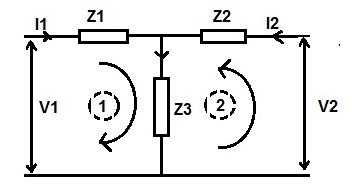
Find the Z parameter for the network shown below.

Solution:
We know that,
V1 = Z11I1 + Z12I2
V2 = Z21I1 + Z22I2
Case1: Assume output port open i.e. I2 =0, voltage across impedance Z3 will be equal to V2.
V2 = Z3I1
Z3 = V2 / I1
But V2 / I1 = Z21, therefore
Z21 = Z3 ……(3)
Also under the condition of output port open, applying Kirchoff’s Loop Law in loop 1,
V1 = I1Z1 + V2
Diving both side of above expression by I1, we get
(V1 / I1) = Z1 + (V2 / I1)
But (V1 / I1) = Z11 and (V2 / I1) = Z21, therefore
Z11 = Z1 + Z21
= Z1 + Z3 [from (3)]
Hence, Z11 = (Z1 + Z3)
Case2: Assume input port open i.e. I1 =0, voltage across impedance Z3 will be equal to V1.
V1 = Z3I2
Z3 = V1 / I2
But V1 / I2 = Z12, therefore
Z12 = Z3 ……(4)
Also applying Kirchoff’s Loop Law in loop 2,
V2 = I2Z2 + V1
Diving both side of above expression by I2, we get
(V2 / I2) = Z2 + (V1 / I2)
But (V2 / I2) = Z22 and (V1 / I2) = Z12, therefore
Z22 = Z2 + Z12
= Z2 + Z3 [from (4)]
Hence, Z22 = (Z2 + Z3)
Hence,
Z11 = (Z1 + Z3), Z22 = (Z2 + Z3), Z12 = Z3, Z21 = Z3 (Ans.)